
Numerical simulation of inclined piles under liquefaction-induced lateral spreading
ABSTRACT
Inclined piles have been widely applied to resist excessive lateral loading in engineering practice. Although some unsatisfactory observations were found in past earthquake events, supportive evidence was also observed in recent years. This paper aims to clarify the performance of inclined piles against liquefaction-induced lateral spreading via the finite element approach. A sloping ground under seismic base excitation is adopted to induce the lateral spreading. A parametric analysis is carried out to study the performance of a 2×1 pile group consisting of vertical and inclined piles. By changing the raked angles of the piles, both symmetric and asymmetric inclined pile groups are considered while vertical pile groups are investigated as reference. The numerical results indicate that inclined piles with appropriate inclinations have better performance than vertical piles when considering the response of the soil-pile-cap system.
INTRODUCTION
In previous large-scale earthquakes, lateral spreading was identified as one of the main causes of damage to pile foundations under bridges and offshore constructions (e.g. Seed et al. 1991; Finn & Fujita 2002). The use of inclined piles was considered as a countermeasure to resist significant horizontal loadings. However, unacceptable performance observed in previous earthquakes (e.g. Seed et al. 1991; Haskell et al. 2013) resulted in the discouragement of the use of inclined piles. Drawbacks of inclined piles, such as residual bending moment, reduction in flexural capacity, large kinematic force and undesirable cap rotation, have been frequently mentioned in engineering practice (Gerolymos et al. 2008).
The benefits of inclined piles were recognised in some recent laboratory studies. Seismic experiments of inclined piles in sand performed by Escoffier et al. (2008), Li et al. (2016a; 2016b), and McManus et al. (2005) provided supportive evidence for inclined piles regarding the enhanced lateral stiffness of the pile foundation and the strengthening of the soil profile. In terms of the numerical investigations of pile foundations against lateral spreading, the Beam-on-Nonlinear Winkler-Foundation approach has been widely adopted, such as by Khosravifar et al. (2014), Shafieezadeh et al. (2012), and Wang & Orense (2014). The three dimensional (3D) finite element method has also been applied extensively, such as by Cheng & Jeremić (2009), Cubrinovski et al. (2008), and McGann et al. (2011). When it comes to inclined piles, most of the numerical studies investigating their dynamic responses were conducted without the consideration of lateral spreading. For instance, Gerolymos et al. (2008), Giannakou et al. (2010), and Sadek & Isam (2006) performed seismic analysis on pile groups with inclined piles in elastic soil deposits numerically. Rajeswari & Sarkar (2019) and Wang & Orense (2019) studied the performance of inclined piles in liquefiable soils through a parametric analysis without being subjected to lateral spreading. Nevertheless, the performance of inclined piles against lateral spreading is still not well established.
To clarify the seismic performance of inclined piles against liquefaction-induced lateral spreading, a parametric study has been carried out through the OpenSees platform (Mazzoni et al. 2007). A sloping ground is adopted to induce lateral spreading while the level ground is studied as reference. Factors considered in this research include the pile inclination, ground slope, and occurrence of soil liquefaction. parametric analysis description
PARAMETRIC ANALYSIS DESCRIPTION
The problem under consideration is a 2 × 1 pile group (Fig. 1a), similar to that employed by Li et al. (2016a; 2016b). The piles have a diameter of D = 0.72 m and a section stiffness of EI = 505 MN·m2. The pile spacing is fixed as 4D = 2.88 m. The pile heads are connected by the cap, which is 1.0 m above the soil surface, with a lumped mass of 100 ton. The fully-saturated soil deposit contains two soil layers: 12.0 m thick dense sand sublayer (relative density Dr = 80%) and medium-dense sand upper-layer (Dr = 55%). The 1995 Kobe earthquake motion (Fig. 1c) is scaled to different amplitudes (amax,base = 0.1g or 0.3g) and used as base excitation towards the x-axis. By applying different inclinations of the left and right piles (i.e. αL and αR ranging from 0°, 5°, 10°, 15°, 20°, and 25°), three pile group configurations are investigated, including “IV” (inclined left pile + vertical right pile), “VI” (vertical left pile + inclined right pile), and “II” (two symmetrically inclined piles). For example, Figure 1a shows a pile group configuration VI with αL = αR = 15°, and the corresponding 3D numerical model in OpenSees is demonstrated in Figure 1b. Additionally, the configuration with two vertical piles (“VV”, i.e. αL = αR = 0°) is also analysed for comparison purposes. In addition to the level ground case, sloping ground (i.e. surface slope β = 2° or 4°) is considered to induce lateral spreading towards the x-axis. Due to symmetry along the y-axis, only half of the model is simulated, and laminar boundaries are adopted. Besides, a free drainage boundary is applied at the ground surface. The modelling details regarding the boundary conditions, soil constitutive model (Pressure-Dependent Multi-Yield surface material for Nevada sand), pile modelling, soil-pile interface, and validation process can be found in the work of Wang & Orense (2019).

Figure 1: Problem definition (all dimensions in metre): (a) geometry for pile configuration II with αL = αR = 15°; (b) numerical model layout; and (c) normalised Kobe earthquake acceleration time history
RESULT ANALYSIS
A parametric analysis is conducted to investigate the responses of soil, cap, and piles. To reflect the performance of inclined piles and evaluate quantitatively the influence of pile inclinations on the system response, a performance index P (in percentage) is adopted, based on Li et al. (2016a; 2016b):
(1)
where QV and QI are the calculated quantities for pile groups with vertical (i.e. αL = αR = 0°) and inclined piles (i.e. αL ≠ 0° or αR ≠ 0°), respectively. Therefore, a positive or negative index indicates the increase or decrease, respectively, of the investigated system response due to pile inclination.
Soil response
The soil responses considered in the interpretation include the excess pore water pressure ratio (ru) and the lateral deflection (Usoil) at different depths. Note that the pore pressure is derived from the free field and the soil center under the cap node (i.e. point A to B in Fig. 1b).
The distributions of the maximum ru in the free field and in cases with vertical piles are presented in Figures 2a and 2b, respectively. The ground slope and amplitude of the input motion are shown in the legends (e.g. “4S-0.3g” means β = 4° and amax,base = 0.3g). The depth indicated in the figures is measured from the ground surface. It can be seen from Figure 2a that soils above 6 m depth liquefy in cases with amax,base = 0.3g, although a slight reduction can be seen for steeper slopes. With amax,base = 0.1g, however, the soil deposit does not liquefy. Therefore, cases with amax,base = 0.1g are classified as “non-liquefied” cases, while the rests are “liquefied” cases. As presented in Figure 2b, the presence of vertical piles in liquefied cases reduce the maximum ru significantly, which can be attributed to the strengthening effects of pile groups on the soil.
The distributions of the maximum ru from cases with pile configuration II in the level ground scenario are demonstrated in Figures 2c-2d. The increasing inclination of the pile reduces the maximum ru in the upper part of the medium-dense soil layer, which may be due to the increased lateral stiffness of the inclined piles. Note that this reinforcement effect of inclined piles on liquefiable soil deposits was also observed in the shaking table experiments performed by McManus et al. (2005). However, the pile inclination promotes the development of maximum ru at deeper depths in the liquefied cases (Fig. 2d). The stiffening effect of the piles is weakened as inclined piles are further away from the observation points (i.e. A-B at the soil centre).
The maximum soil deflections in cases of the free ground and pile configuration VV are shown in Figure 3. Varying magnitudes of lateral deflection have been induced due to soil liquefaction. In Figure 3a, sharply increasing deflections can be observed at 8 m depth which is the interface of the two soil layers. With the presence of piles, the deflections near the interface, shown in Figure 3b, change gently with the depth. To investigate the influence of pile inclination, the performance index for soil deflection, PUsoil, is evaluated based on Equation 1 and illustrated in Figure 4. The pile inclination α represents αL, αR, and αL = αR for pile configurations IV, VI and II, respectively. Most indices are negative and decrease with the pile inclination, i.e. that the presence of the inclined piles reduces the soil deflection, with larger pile inclinations enhancing such beneficial effect. The indices in Figures 4b-4c are generally lower than those in Figure 4a, which indicates that inclined piles in sloping grounds have more pronounced beneficial effects than in the level ground. The beneficial effects of the configuration VI (PUsoil is down to -50%) are more pronounced than those of the configuration IV (PUsoil is down to -37%) but less pronounced than those of the configuration II (PUsoil is down to -60%). The soil deflection is mitigated by the inclined piles due to the larger lateral stiffness. Moreover, pile groups with one pile inclining in the upslope direction are more beneficial to the ground in terms of the soil response. Besides, indices for the liquefied cases are generally lower than in non-liquefied cases, showing that inclined piles have more pronounced beneficial effects when the soil liquefies.
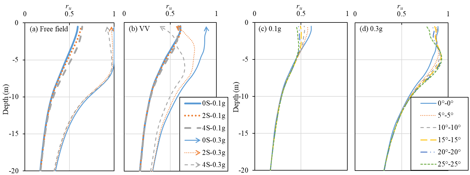
Figure 2: Distributions of the maximum ru in soil
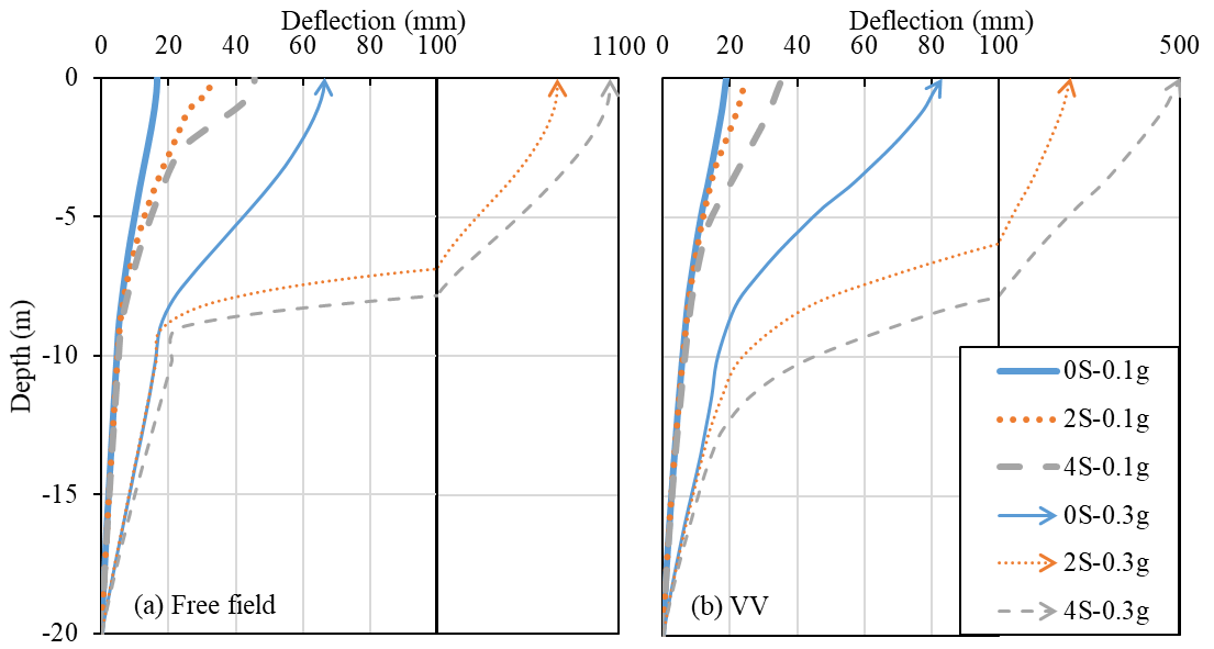
Figure 3: Distributions of the lateral deflection of soil

Figure 4: Performance index for the maximum soil deflection
Cap response
The lateral displacement (Ucap) and rotation (θ, the rotation of the cap node is along the y-axis) of the cap are investigated here. The corresponding performance indices (i.e. PUcap, and Pθ) are presented in Figures 5-6.
The negative PUcap shows beneficial effects on the cap which is also observed in other numerical studies (e.g. Giannakou et al. 2010; Li et al. 2016a, 2016b; Sadek & Isam, 2004). Inclined piles are more beneficial in the sloping ground than in the level ground, as the indices shown in Figures 5b-5c are lower than those in Figure 5a. Besides, the configurations II and VI show more beneficial effects than the configuration IV.
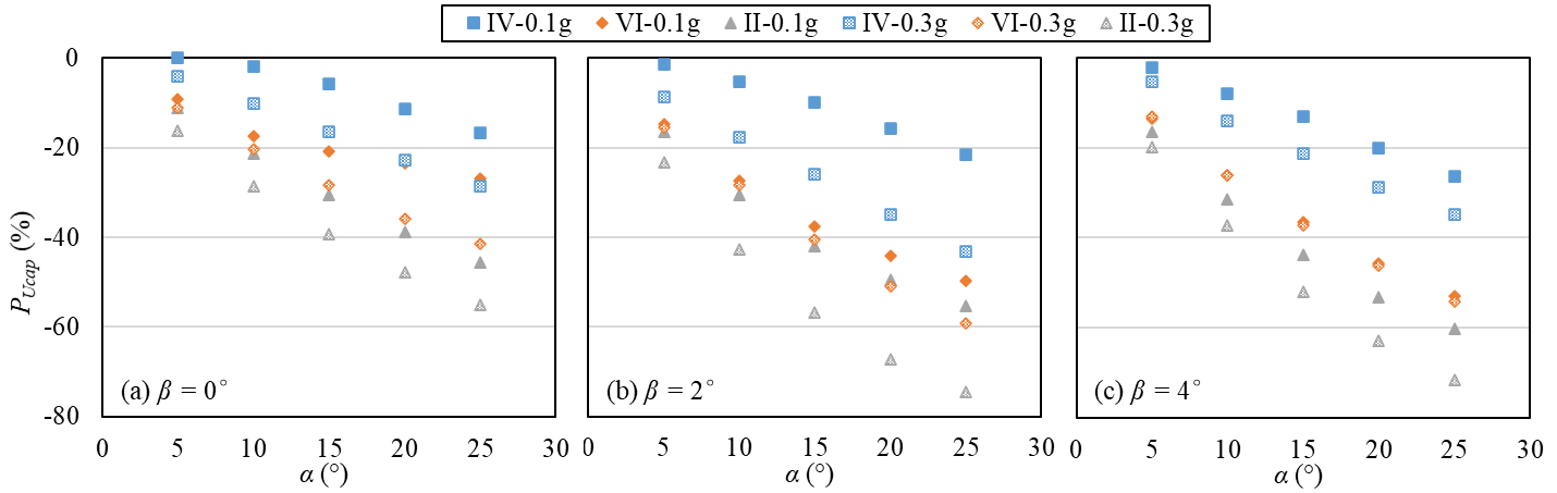
Figure 5. Performance index for the maximum lateral deflection of cap
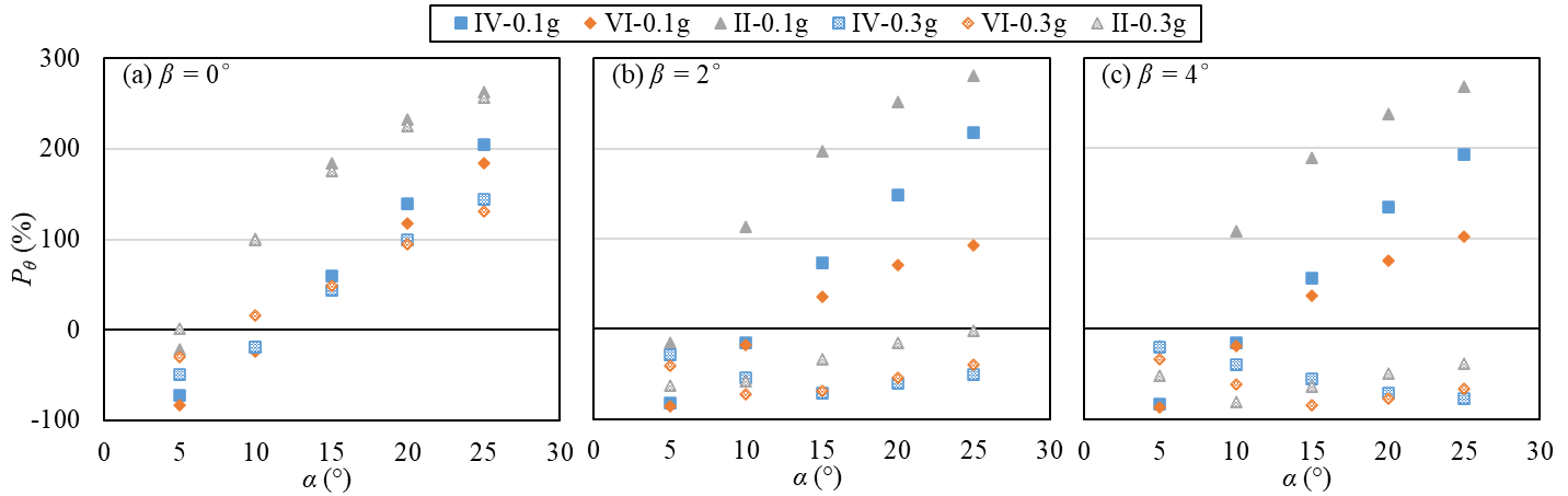
Figure 6. Performance index for the maximum rotation of cap
As shown in Figure 6, the cap rotation in the level ground (Fig. 6a) decreases for small pile inclinations (α < 10°). For example, indices for cases with α = 5° are down to -83%, while those for cases with α = 25° are up to 256%. It is noted that the use of inclined piles often induces considerable cap rotation, as indicated by Giannakou et al. (2010) and Li et al. (2016a). For the liquefied sloping ground cases, indices are negative, indicating a beneficial effect. The configurations IV and VI induce lower Pθ than the configuration II, with the exception of cases with α < 10° in liquefied sloping ground. This result indicates that a combination of vertical and inclined piles is generally better than the symmetrically-inclined pile groups in terms of the cap rotation.
Pile response
The pile response investigated in this study includes the maximum bending moment M and shear force FS in the piles. The corresponding performance indices (i.e. PM and PFS) are also investigated.
Maximum bending moment
Figure 7 presents the maximum bending moment profiles experienced by the inclined right pile of configuration VI. The maximum bending moment increases significantly with the slope inclination. The peak values generally occur at the pile heads, except for cases with a large ground slope (i.e. Figs 7e-7f) in which the locations of the peak values are closer to the interface of the two soil layers (i.e. 8 m depth). The increase in pile inclination generally reduces the bending moment at the pile heads and around the layer interface. The decreased bending moment at the pile head is in accordance with those reported in the literature (e.g. Gerolymos et al. 2008; Giannakou et al. 2010; Li et al. 2016a, 2016b; Sadek & Isam, 2004). Giannakou et al. (2010) explained that the prevalence of inertial loading results in such smaller bending moment.
Figure 8 shows the corresponding performance indices for the maximum bending moment PM. In the non-liquefied level ground cases, only configuration II induces lower maximum bending moment. In other cases, however, both configurations VI and II are beneficial. The increase in pile inclination generally induces more pronounced effects in non-liquefied cases but have minor impacts in liquefied cases. Based on the investigation of Giannakou et al. (2010), the liquefied soil will result in a large pile-soil stiffness ratio, and thus the additional stiffness provided by the inclined piles has only minor influence on the system response.
Maximum shear force
Figure 9 demonstrates the maximum shear force profiles for the left pile of configuration II. It is observed that the shear force profiles are amplified significantly with the increase in ground slope. Locations of the peak maximum shear force are generally in the lower part of the medium-dense soil layer. The pile inclination tends to enlarge the maximum shear force at the pile head and lower locations (e.g. at 4 – 8 m depth) in the liquefied cases (i.e. Figs 9d-9f) but tends to decrease those in the non-liquefied cases (i.e. Figs 9a-9c). It is worth noting that due to the adoption of a frictional interface between the pile tips and adjacent soil, the pile tips show non-zero shear forces although they have free ends.
The corresponding performance indices for the maximum shear force PS are demonstrated in Figure 10. In non-liquefied cases, the pile configurations VI and II are beneficial in reducing the maximum shear force. In the liquefied level ground, the presence of the inclined piles increases the maximum shear force by 34% at most. With the increase in the slope inclination, however, this detrimental effect becomes less pronounced and even turns to be beneficial overall, with the exception of the configuration IV. Therefore, in terms of the maximum shear force, the pile inclination in configurations VI and II has a beneficial effect in the sloping ground and non-liquefied level ground cases.
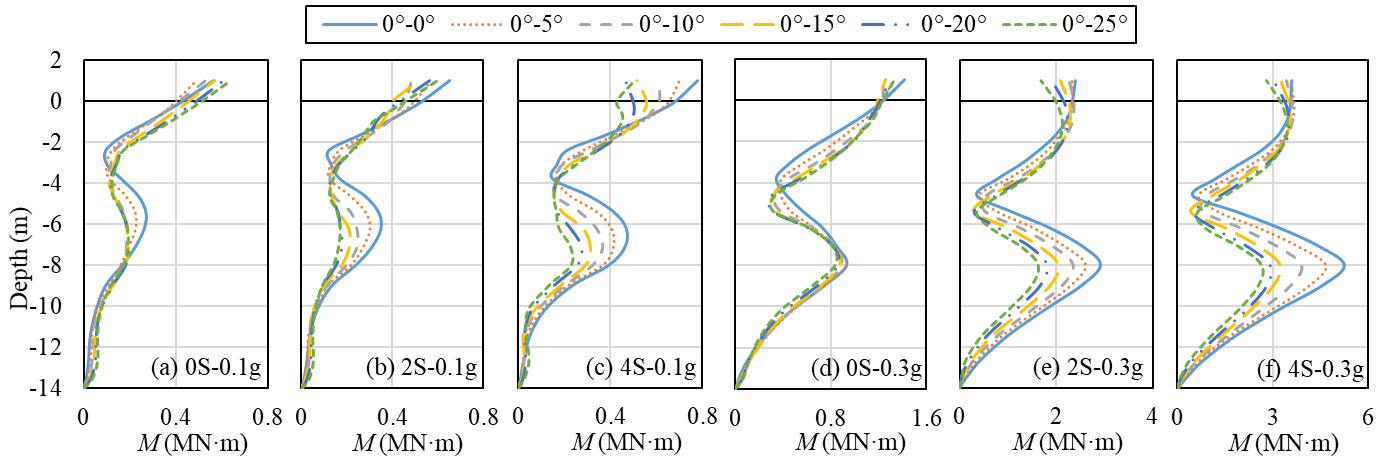
Figure 7. Distribution of the maximum bending moment developed in the right pile for configuration VI
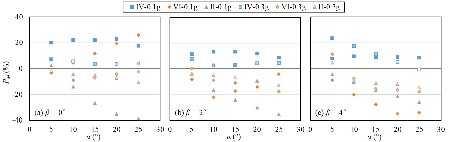
Figure 8. Performance index for the maximum bending moment
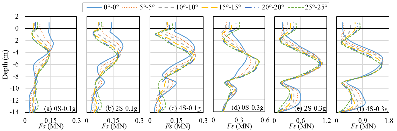
Figure 9. Distribution of the maximum shear force developed in the left pile for configuration II
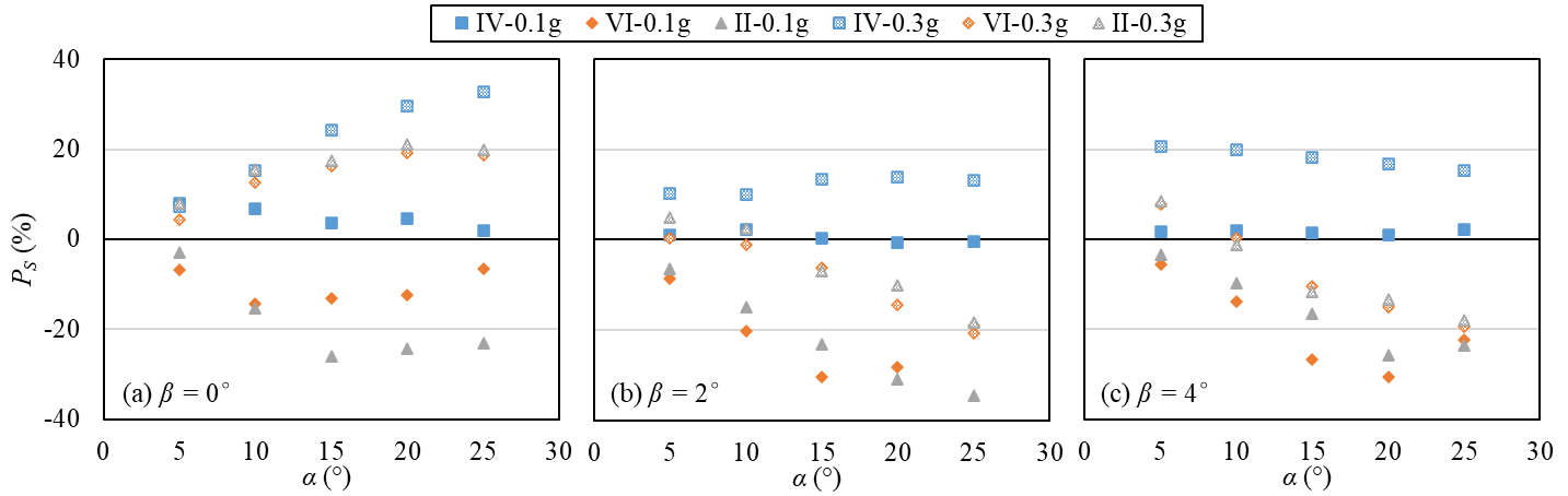
Figure 10. Performance index for the maximum shear force
CONCLUSIONS
This paper investigated the seismic performance of inclined piles when subjected to liquefaction-induced lateral spreading through a parametric FEM analysis. The primary outcomes are as follows:
- In the sloping ground scenario, better performance can be found with the use of pile group configurations “II” (two symmetric inclined piles) and “VI” (the combination of vertical and inclined piles with the inclined pile downslope).
- In the non-liquefied ground case, the use of inclined piles with appropriate configurations (i.e. VI and II) can be beneficial for most of the soil-pile system responses, except for the cap rotation. However, inclined piles with small inclinations (i.e. < 10°) can also be beneficial for the cap rotation.
- With the presence of large lateral spreading (liquefied sloping ground), inclined piles are found to be beneficial in reducing the response of soil-pile system regarding the lateral deflection of soil and cap, cap rotation, shear force and bending moment of the pile.
Within the scope and conditions investigated in this paper, inclined piles, when used at appropriate configurations, could produce better performance for the soil-pile system when subjected to liquefaction-induced lateral spreading.
ACKNOWLEDGMENT
The authors wish to acknowledge the contribution of NeSI high-performance computing facilities in this research. NZ’s national facilities are provided by the NZ eScience Infrastructure and funded jointly by NeSI’s collaborator institutions and through the Ministry of Business, Innovation & Employment’s Research Infrastructure programme (https://www.nesi.org.nz).
REFERENCES
Cheng, Z. & Jeremić, B. 2009. Numerical modeling and simulation of pile in liquefiable soil. Soil Dynamics and Earthquake Engineering, 29(11–12): 1405-1416.
Cubrinovski, M., Uzuoka, R., Sugita, H., Tokimatsu, K., Sato, M., Ishihara, K., Tsukamoto, Y. & Kamata, T. 2008. Prediction of pile response to lateral spreading by 3-D soil-water coupled dynamic analysis: Shaking in the direction of ground flow. Soil Dynamics and Earthquake Engineering, 28(6): 421-435.
Escoffier, S., Chazelas, J. L. & Garnier, J. 2008. Centrifuge modelling of raked piles. Bulletin of Earthquake Engineering, 6(4): 689-704.
Finn, W. D. L. & Fujita, N. 2002. Piles in liquefiable soils: seismic analysis and design issues. Soil Dynamics and Earthquake Engineering, 22(9): 731-742.
Gerolymos, N., Giannakou, A., Anastasopoulos, I. & Gazetas, G. 2008. Evidence of beneficial role of inclined piles: Observations and summary of numerical analyses. Bulletin of Earthquake Engineering, 6(4): 705-722.
Giannakou, A., Gerolymos, N., Gazetas, G., Tazoh, T. & Anastasopoulos, I. 2010. Seismic Behavior of Batter Piles: Elastic Response. Journal of Geotechnical and Geoenvironmental Engineering, 136(9): 1187-1199.
Haskell, J. J. M., Madabhushi, S. P. G., Cubrinovski, M. & Winkley, A. 2013. Lateral spreading-induced abutment rotation in the 2011 Christchurch earthquake: observations and analysis. Géotechnique, 63(15): 1310-1327.
Khosravifar, A., Boulanger, R. W. & Kunnath, S. K. 2014. Effects of liquefaction on inelastic demands on extended pile shafts. Earthquake Spectra, 30(4): 1749-1773.
Li, Z., Escoffier, S. & Kotronis, P. 2016a. Centrifuge modeling of batter pile foundations under earthquake excitation. Soil Dynamics and Earthquake Engineering, 88: 176-190.
Li, Z., Escoffier, S. & Kotronis, P. 2016b. Centrifuge modeling of batter pile foundations under sinusoidal dynamic excitation. Bulletin of Earthquake Engineering, 14(3): 673-697.
Mazzoni, S., McKenna, F., Scott, M. H. & Fenves, G. L. 2007. OpenSees command language manual. Pacific Earthquake Engineering Research (PEER) Center.
McGann, C. R., Arduino, P. & Mackenzie-Helnwein, P. 2011. Applicability of conventional p-y relations to the analysis of piles in laterally spreading soil. Journal of Geotechnical and Geoenvironmental Engineering, 137(6): 557-567.
McManus, K., Turner, J. & Charton, G. 2005. Inclined reinforcement to prevent soil liquefaction. In Proceedings of the Annual NZSEE Technical Conference. Wairakei, New Zealand.
Rajeswari, J. S. & Sarkar, R. 2019. Seismic response of batter piles in liquefiable soils. In Proceedings of the 7th International Conference on Earthquake Geotechnical Engineering. Roma, Italy, 4629-4636.
Sadek, M. & Isam, S. 2004. Three-dimensional finite element analysis of the seismic behavior of inclined micropiles. Soil Dynamics and Earthquake Engineering, 24(6): 473-485.
Seed, R. B., Dickenson, S. E. & Idriss, I. M. 1991. Principal geotechnical aspects of the 1989 Loma Prieta earthquake. Soils and Foundations, 31(1): 1-26.
Shafieezadeh, A., DesRoches, R., Rix, G. J. & Werner, S. D. 2012. Seismic performance of pile-supported wharf structures considering soil-structure interaction in liquefied soil. Earthquake Spectra, 28(2): 729-757.
Wang, S. & Orense, R. P. 2014. Modelling of raked pile foundations in liquefiable ground. Soil Dynamics and Earthquake Engineering, 64: 11-23.
Wang, Y. & Orense, R. P. 2019. Numerical analysis of inclined pile group performance in liquefiable sands. In Proceedings of the 7th International Conference on Earthquake Geotechnical Engineering. Roma, Italy, 5630-5637.