Detailed Design of Land Reclamation over soft ground in a seismically active environment at Lyttelton Port of Christchurch
Abstract
In fulfilling its vision and purpose Lyttelton Port of Christchurch (LPC) intends to create new land in Te Awaparahi Bay through a land development programme. The programme involves reclamation of approximately 34ha of new land and the construction of a new 700m wharf, to be built in two stages. The proposed approximate 100m deep piled wharf structure will be subject to both residual land consolidation movement and seismic loading. As the required consolidation completion depends on the acceptance of the proposed wharf structure capacity, the key challenge is how can we accelerate the expected consolidation settlement and achieve a cost-effective wharf structure in the proposed development timeframe? The major component of the detailed design comprised the land reclamation including 60m soft ground treatment, its seismic response and to ensure the proposed wharf is feasible following land reclamation development under seismic and static condition. The ground model and material parameters have been further explored. Sophisticated numerical analyses were carried out to assess stability, consolidation deformations, seismic time history analysis and soil/structure interaction under static and dynamic seismic loading, and a surcharge program was designed to achieve settlement requirements prior to wharf construction.
Specifically: the consolidation settlement back analysis was carried out to compare with the ongoing monitoring to develop the surcharge design. The liquefaction analysis, one-dimensional and two-dimensional seismic time history response analyses have been undertaken to assess the response of the reclamation and the wharf structure to likely dynamic seismic loading. A dynamic soil-structure interaction analyses between the wharf pile structure and ground has been carried out to determine the proposed wharf reaction. This paper summaries the key steps in the analysis development and outlines the innovation of the land reclamation design at LPC.
Figure 1: Project general layout (left) and proposed wharf structure (right)

1 INTRODUCTION
Lyttelton Port of Christchurch (LPC) is embarking on a long-term plan to develop a modern container terminal at Te Awaparahi Bay. The first stage of works will reclaim 16ha of land and construct a 350m long wharf which is intended to be operational by 2024. A traditional wharf with revetment will be constructed and supported on five rows of piles driven to around 100m depth.
Coffey Services (NZ) Limited (Coffey) has been involved with the project in a specialist geotechnical consulting role since early 2014, when is commissioned to provide a concept design through to the present day where our current engagement comprises of a detailed stage 1 geotechnical design of the land reclamation, and interaction analysis of the soil/structure. The modelled wharf pile structure and its geometry/spacing is based on sections provided by the Structural Engineer. Figure 1 below indicates the general layout and proposed wharf structures considered in the detailed design.
The completed detailed design led us to carry out the following key activities:
- Comprehensive site investigation and laboratory testing, including monotonic and cyclic testing;
- Back analysis for consolidation settlement of the existing and new reclamation with ongoing data monitoring;
- Bund and dredging design under both static and seismic conditions;
- Surcharge design for both land reclamation and the proposed wharf structures;
- Liquefaction analysis and seismic time history analysis to combine with the above activities
- Interaction analysis of the reclaimed soil and the proposed wharf structures under seismic conditions
Preloading and surcharge were selected as appropriate ground treatment approaches from the outset of the conceptual design through to the completion of the detailed design phase. The reclamation as well as the operational loads from the wharf are expected to induce movements in the soft marine sediments leading to excessive lateral loads on the wharf and piles. Surcharging of the reclamation prior to wharf construction was therefore required in order to accelerate consolidation prior to installation of the piles and the wharf. For land reclamation combined with wharf structure, the consolidation completion level depends on the proposed wharf structure capacity to resist the the reclamation land residual settlement (Dai 2008 and 2012). Prior to wharf construction it was typically required that 70% of total settlement should be complete based on Coffey’s original concept design phase. However, critical to the design is an understanding of the reaction on the pile from the residual post construction settlements and seismic loads. It became apparent that 70% completion of the consolidation could potentially be unconservative in high seismic areas where significant amounts of settlement were possible. The detailed design has therefore assessed the reaction on the pile from both 70% and 95% consolidation completion coupled with seismic responses.
To accurately estimate the seismic response of the reclaimed land and the proposed wharf structure, the dynamic time history analyses based on 11 recorded earthquake data sets were performed using different approaches. Dynamic interaction analyses of reclamation soil/wharf structure were carried out to determine what the required consolidation level would be to ensure the proposed wharf is safe and serviceable.
The following sections discuss the key design and analysis components of the above procedure.
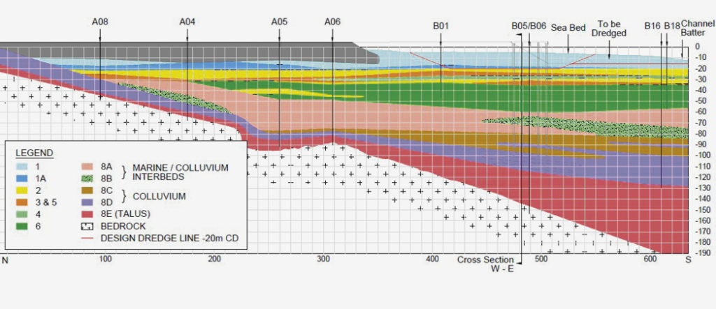
Figure 2: North-South cross section showing existing reclamation, proposed wharf and Te Bay geology
2 Geological Setting and design parameters
The project has benefited from a relatively comprehensive on-shore and offshore site investigation and laboratory testing programme. This was carried out between 2015 and 2017. The investigation included on-shore and off-shore boreholes drilled to a maximum depth -170m CD, Cone Penetration Tests to -58m, CPTu tests, Dilatometer testing, downhole shear wave velocity testing, settlement monitoring at the existing reclamation and laboratory testing (soil indices, triaxial tests, direst shear, unconfined compression tests, monotonic loading tests).
The upper ground profile in the bay area generally consists of fine grained relatively young marine sediments (silt, clay and interbedded fine sand layers). The deposits are dominated by normally consolidated fine grained materials (silt and clay) with units designated 1,1a, 4 and 6 being compressible. Interbedded layers of sand are encountered through the ground profile and are associated with a gradual change in environment from a deeper marine to a near shore environment where wave action has higher energy and hence sandier soils are observed. Below the marine deposits lie volcanic derived colluvium overlying weathered volcanic rock (typically basalt). The geological N-S cross section is presented in Figure 2.
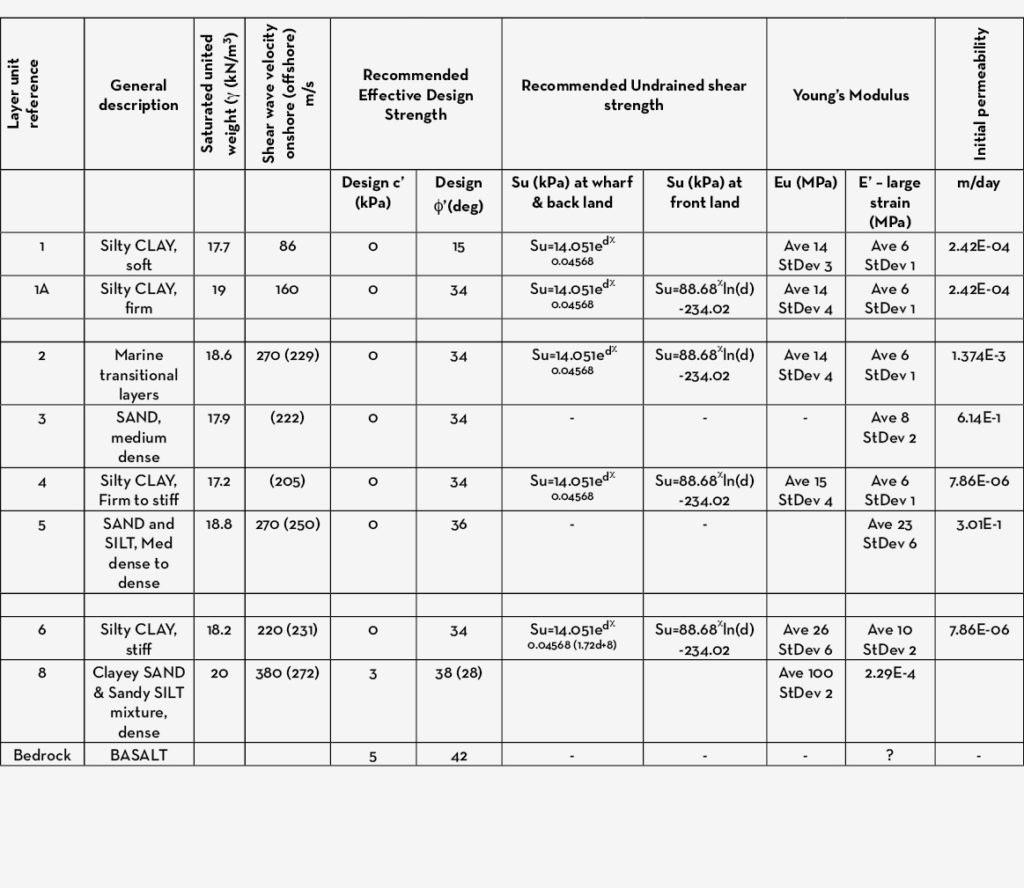
The deriving of design parameters is included in the unpublished report (Coffey 2017). The major outputs are summarised in the table 1 below:
Table 1: Typical geotechnical parameters
3 Consolidation settlement back-Analysis and Surcharge Design
3.1 Analysis
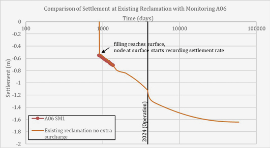
The surcharge design was first analysed using Coffey’s in house program CONFED which is a 1D based method to provide a benchmark for the more detailed 2D analysis using Plaxis 2D. Each method used back analyses of material parameters to match the observed settlement at a monitoring plate on the existing reclamation. Measured monitoring results at a monitoring plates were available from their installation in March 2016 to August 2017 (the detailed design phase). The previous existing reclamation is assumed to have reached the monitoring station location in October 2013 therefore fill placement and settlement had been under way for around 2.5years prior to the start of monitoring. Back-analysis of settlement rates and material parameters indicated that around 550mm of settlement had already occurred prior to plate installation.
Total settlements after 100years were predicted to be approximately 1.77m at the existing reclamation and 1.85m at the bund. A surcharge loading programme was then designed to achieve the design criteria of 70% of total consolidation by stage 1 wharf completion in 2024. Figure 3 shows a typical example of how time vs settlement and pore water pressure increases with each application of surcharge load, followed by dissipation of excess pore water pressures and corresponding increases in effective stress.
The results indicate that a surcharge of 0.7m of fill would be required to meet the design criteria of 70% consolidation settlement completion at the existing reclamation. However, at the bund and new reclamation even a surcharge of 9.0m of fill would only achieve 55% completion of the consolidation by 2024. Plaxis 2D was used to analyse this problem in more detail.
Figure 3: Typical plot of time vs settlement and excess pore water pressure, effective and total stress at bund following additional surcharging.

3.2 2D CONSOLIDATION ANALYSIS USING PLAXIS 2D
3.2.1 2D Analysis methods
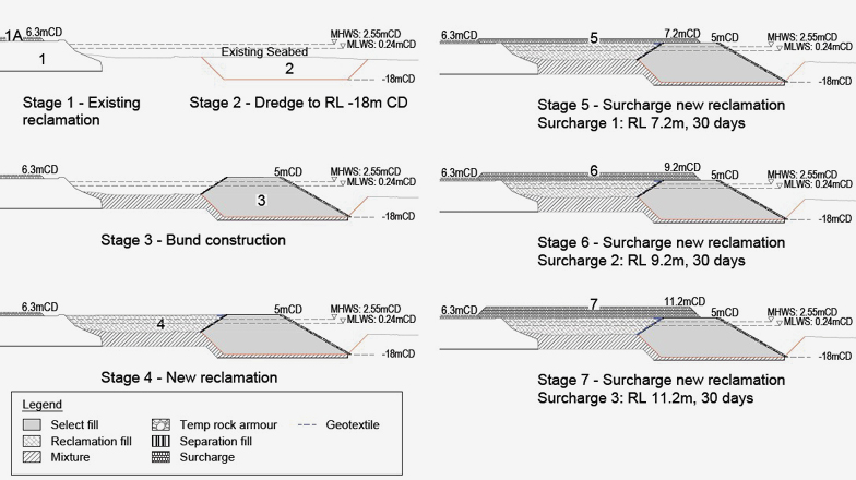
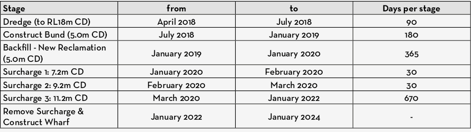
The settlements associated with reclamation construction and operational loads have been assessed in Plaxis 2D v.2017. The construction sequence is illustrated in Figure 4 and the analysis model is shown in Figure 5. It includes the following steps:
- Initialization of stresses across virgin seabed prior to reclamation.
- Emulation of the existing reclamation by construction in 4 stages over 6.5years (2011 to the present day).
- Back-analysis of material stiffness and permeability to match settlement monitoring at the edge of the existing reclamation (outputs see Figure 6).
- Emulation of the new reclamation with dredging to -18.0m CD and bund construction in 3 stages over 2.5 years to design level RL +5m CD.
- Application of working loads; 12kPa 9.0m back from bund crest, and 55kPa across the backland.
- Post construction consolidation to achieve >99% degree of consolidation across the model.
3.2.2. 2D Analysis Results
Settlements following application of operational loads but with no additional surcharge are predicted to be in the order 1.64m at the existing reclamation and 1.88m immediately behind the bund which is in good agreement with the 1D results.
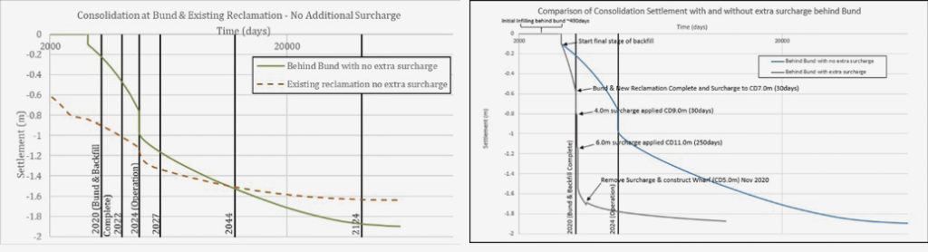
The analysis shows that consolidation at the existing reclamation is likely to be 70% complete by 2024 (Table 2 and 7 left). However, the bund and new reclamation with no surcharge is less than half complete, and therefore requires additional surcharging prior to wharf construction.
Figure 4: Designed construction sequences.
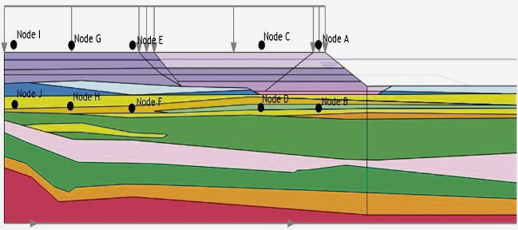
Figure 5: Plaxis model used in settlement analysis.
Figure 6: Settlement near crest of existing reclamation with model parameters back-analysed to match observed settlements.
3.3 Bund and New Reclamation Surcharge Design
A surcharge loading programme was designed in Plaxis 2D by adding a series of distributed loads above the design level of 5m CD, to simulate placement of fill. Settlement was calculated between each load application and the loads and hold times were iterated to achieve 70% and 95% consolidation by 2024.
The surcharge design which achieves 95% consolidation is shown in Table 3 and must be left in place until January 2022 as a minimum, and can be removed any-time after this date to suit the wharf construction program.
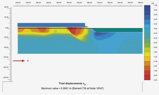
Figure 7 (right) shows settlement behind the bund with and without the surcharge illustrating how the extra surcharge accelerates the consolidation settlement and achieves the design criteria. Figure 8 presents Plaxis output showing vertical settlement at 95% completion
in 2024.
Table 2: Settlements with no additional surcharge (operational loads only)
Table 3: Surcharge design at bund at new reclamation.
Figure 7: (Top) Settlements under operational loads with no additional surcharge; (Above) Comparison of Consolidation Settlement with and without Extra Surcharge Behind Bund.
Figure 8: Plaxis output of vertical settlement at 95% complete at 2024

4 Reaction on proposed wharf structure under static conditions
Lateral soil movements will continue to occur at the bund as the soils continue to settle following the completion of wharf construction. These further lateral ground movements will induce a lateral reaction on the wharf piles in addition to any seismic load. The static bending moments and shear forces induced in the piles (following construction of the wharf) due to on-going consolidation have been modelled in Plaxis 2D.
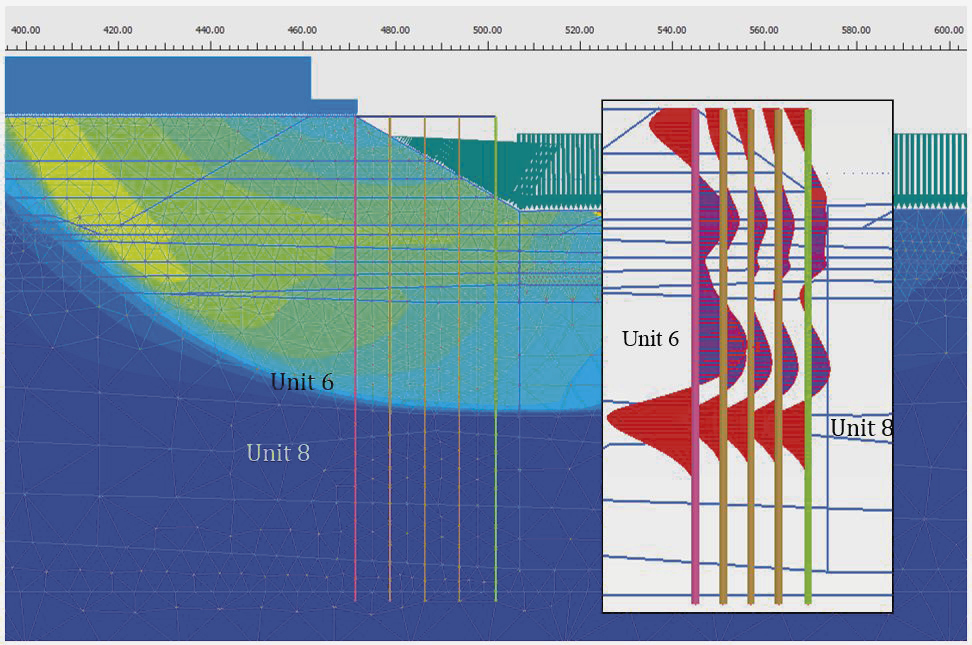
Figure 9 shows that the maximum reaction on the piles due to consolidation movement is between Unit 6 and Unit 8 (about -60m CD). This is due to the significant differential movement contrast in this area with the major consolidation movement occurring in Unit 6 (silt/clay), compared with the very minor movement that takes place in Unit 8 (very stiff colluvium).
Figure 9: Consolidation movement along the boundary of Unit 6 and Unit 8 superimposed with static pile bending moment – max. moment was near the interface of Unit 6 and Unit 8.
5 REACTION ON PROPOSED WHARF STRUCTURE under seismic condition
An important aspect of the pile design is to consider the induced reaction in the piles from the seismic soil movement.
5.1 Liquefaction analysis
A liquefaction assessment of soils within the Te Awaparahi Bay has been undertaken based on the methods of Bray and Sancio (2006), Boulanger and Idriss (2014) and Andrus & Stokoe (1997) for the four average exceedance probabilities presented in Table 4 below
Table 4: Liquefaction analysis assessment Parameters.
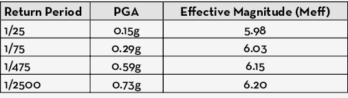

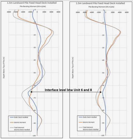
Figure 10: (left) – Moment for 70% consolidation completion; (right) – Moment for 90% consolidation completion.
The analysis indicates that liquefaction potential is low. Liquefaction induced free-field vertical settlement within the sandier layers are also low with settlements in the range of 15-50mm over the depth of the CPTs (typically 45 to 60m depth) across most design events.
Seismic design
Following on from the concept design phase (Antonopoulos I.K. & B.H. Cheah, 2017), the detailed seismic design was carried out using Performance Based Design and full soil-foundation-structure-interaction methods. The design follows a series of steps to capture the performance under a suite of eleven (11) critical earthquake time histories (deconvoluted as necessary) selected to represent near field, regional and Alpine Fault events.
A one-dimensional soil amplification analysis has been undertaken to assess the new stratigraphy’s response under the selected time histories and to be used as a benchmark for calibration and comparison of the 2D analyses. Both Equivalent-linear (EL) and non-linear (NL) methods were used. The EL analyses were performed using software Shake2000 (Ordóñez, 2012), and the NL analyses were performed using software D-Mod2000 (Matasović and Ordóñez, 2011). Details regarding earthquake record time histories, deconvolution, and motion scaling are referred to in the report (Coffey 2017).
Based on the results of the 1D soil amplification analysis, the most critical records were:
Lixouri 2014, which exhibits a significant forward directivity component, and Kaikōura 2016, recorded within the Wellington Port basin, which exhibits both long duration and basin reflection effects.
These were selected as input motions for the 2D time history analyses that were carried out to assess the performance of the concept design wharf structure against the new reclamation.
Performance of proposed wharf structure under both residual settlement and seismic loading
Time history analyses and soil-foundation-structure-interaction of the proposed wharf has been undertaken using the 2D finite difference software FLAC. The model is setup around a representative north-south section through the proposed reclamation and the wharf. The modelled wharf structure geometry and spacing is based on a typical wharf section in Figure 1.
The 2D analyses have been carried out with both the Lixouri (2014) and the Kaikōura (2016) input motions and have been compared with the 1D benchmark. Both resulted in very similar and comparable results albeit the Kaikōura motion takes considerable computation time due to its duration. Therefore, the Lixouri (2014) time history was selected as the final input motion for the design.
The time history and soil-foundation-structure-interaction analyses results include bending moments, shear forces and displacements for the wharf piles. Combined with reactions from the residual consolidation settlement in section 4, and the time history analysis in this section, Figure 9 below illustrates the distribution of bending moments along the landward pile, which is the worst case when compared to both seaward and internal piles across the wharf structure.
As can be seen in Figure 10, at the interface level between Units 6 and 8, the cumulative bending moment (static + seismic) was about 4MNm/pile for 70% consolidation movement completion. Considering the proposed pile dimension of 1.5m diameter with a 25mm thick steel tube pile, the reaction in the pile may have overstressed the section when compared to its capacity.
However, the cumulative moment at this elevation for 90% consolidation was approximately 2MNm/pile, which should be less than the proposed pile capacity. Accordingly, to minimise the reaction on the pile, it has been recommended that 90% completion of consolidation should be achieved before wharf construction commences.

6 Conclusion
The current land reclamation design faces challenges from deep soft ground consolidation settlement, a seismically active environment and client operation timeframe requirements. These items are also relevant to the interaction analysis with the proposed wharf structures. The land reclamation design included a comprehensive suite of analysis. A back analysis was carried out to determine the consolidation timeframe and residual deformation. Plaxis 2D analysis was also performed to identify the reaction on the proposed wharf structure under residual reclamation land deformation. Full time history analyses were carried out, and the selected Lixouri (2014) event was used as input motion to the 2D finite difference software FLAC to determine the performance on the wharf piles and reclamation under seismic loading. The reactions along the proposed piles combined the results of both residual static deformation and seismic loading.
Based on the detailed analyses with the proposed wharf structure capacity, a consolidation completion of 90% is required. A rational and detailed schedule of fill heights with staying times was also designed as in Figure 4.
The completed detailed design can be directly extrapolated into the Stage 2 land reclamation and proposed wharf structure design for Lyttelton Port of Christchurch. It is believed that the design and analysis experience can be applied to similar infrastructure design in New Zealand.
7 Acknowledgement
The writers wish to thank Lyttelton Port of Christchurch for their approval to publish this paper.
Reference
Dai, C., 2008, Bulkhead wall design on very soft clay ground, Continuum and Distinct Element Numerical Modelling in Geo-Engineering – Hart, Detournay & Cundall (eds.) Paper: 11-01 ©2008 Itasca Consulting Group, Inc., Minneapolis, ISBN 978-0-9767577-1-9
Dai, C., 2012, Wharf Bulkhead Wall Geotechnical and Structural Capacity Assessment, Journal of Australian Geomechanics Society.
Coffey (2017), Design Report on LLPC Te Awaparahi Bay Stage 1 Land reclamation, 773-CHCGE208087AA, Christchurch, NZ
Plaxis v2017, Delft, The Netherlands
Antonopoulos I.K. & B.H. Cheah, 2017. Seismic design of the Te Bay Reclamation of the Lyttelton Port of Christchurch. PBD-III Vancouver 2017
Bray, J.D. and Sancio, R.B., 2006, Assessment of the Liquefaction Susceptibility of Fine-GrainedSoils, J. Geotech. Geoenvironment. Eng., 132(9): 1165-1177
Boulanger, R. W. and Idriss, I. M., 2014, CPT and SPT Based Liquefaction Triggering Procedures, Center for Geotechnical Modeling Department of Civil and Environmental Engineering University of California Davis, California
Andrus, R.D., and Stokoe, K.H., 1997., Liquefaction Resistance Based on Shear Wave velocity, NCEER Workshop on Evaluation of Liquefaciton Resistance of Soils, Technical Report NCEER-97-0022. T.L. Youd and I.M. Idriss, Eds., 4-5 Jan 1996, Nat. Ctr. For Earthquake Engrg. Res., Buffalo, NY, pp. 89-128
Geomotions LLC 2016. SHAKE2000
D-Mod2000 Matasović and Ordóñez, 2011
Itasca Consulting Group, Inc. (2016) FLAC — Fast Lagrangian Analysis
of Continua, Ver. 8.0. Minneapolis: Itasca
Originally published:
Antonopoulos I.K. & B.H. Cheah, 2017. Seismic design of the Te Bay Reclamation of the Lyttelton Port of Christchurch. PBD-III Vancouver 2017.Awad A. & I.K. Antonopoulos, 2017. Kawarau Bridge Development in Queenstown. Piling & Deep Foundations New Zealand 2017.
McDermott C., I.K. Antonopoulos, B. Cheah, 2017. Overcoming Soft Ground Conditions at the Lyttelton Port of Christchurch. Australian Coasts & Ports 2017.