
The use of hydrofraise cutter technology to construct diaphragm walls in Auckland
ABSTRACT
Deep basements and structures such as shafts for infrastructure often require embedded retaining walls to allow safe excavation and the control of groundwater. In urban environments the effects of retaining structure deformation and settlement associated with dewatering or groundwater drawdown can be significant factors. In recent years diaphragm walling has proven to be a good solution where soft ground and high groundwater pressures are present. The challenges of weak rocks, space optimization and construction constraints has resulted in the successful deployment of hydrofraise cutter use on a couple of recent projects for the first time in New Zealand.
The paper will cover the following aspects related to hydrofraise cutter technology:
• Outline methodology
• Guidance systems
• Comparison of retaining wall methodologies
• Support equipment
• Project examples
• Challenges
OUTLINE DIAPHRAGM WALLING METHODOLOGY
Diaphragm walling was first developed in the 1950 when the drilling fluid technology from the oil industry was applied in civil engineering to stabilise excavations. The enable the construction of deep rectangular bentonite fill trenches to be formed in unstable soils below the water table. The outline methodology (figure 1) comprises excavation using support fluid, placement of prefabricated reinforcement cage and concreting using the tremie method has not changed. The typical diaphragm wall thickness of 0.6m to 1.2m is excavated in discreet 2.8m or 6.0m to 7.0m length panels with joints between panels. A guidewall is used to aid digging tool positioning, provide safe access, ensure near surface stability given plant loading and support the reinforcement cage. Some significant developments in these fundamental processes have taken place.

Figure 1: Diaphragm wall construction sequence & LRB rig-mounted hydrofraise

Grab excavation of the trench
The use of a rope operated 2.8m length grab suspended from a heavy-duty crane is widely used to dig into the soil and remove the spoil. These grabs are limited to digging soils and very weak rock unless used in conjunction with chiselling when they become slow and can generate unacceptable vibration. Achievable excavation verticality tolerance of 1 in 100 with a grab are aligned to piling tolerances.
Hydraulic grab excavation
The application of hydraulic grab closing mechanisms facilitated the use of heavier and more compact grabs with less impact on the crane. Improved digging rates in some materials is possible and more consistent productivity is achievable with less operational sensitivity. The real benefit of the hydraulic guide systems and associated monitoring instrumentation developed was the ability to improve the verticality digging tolerances. This is reflected in the Specification for piling and embedded retaining walls (Institution of Civil Engineers 2017) which recommends a standard verticality deviation of 1 in 150 for hydraulic grab excavation.
Hydrofraise excavation
In the 1970s hydrofraise technology started to be developed which was a step change as it adopted the reverse circulation approach that uses the support fluid not only to maintain excavation stability but also to transport of the excavated spoil. To achieve this the soil or rock must be broken up so that it can be maintained in suspension within the support fluid as it is pumped to the surface. As the digging tool was not being used to remove the spoil the excavation rate was not affected by the depth and it was possible to excavate deeper and faster.
The use of rotary “milling” action is well aligned with the need to break up the soil and, with careful selection of drums and teeth, the excavation of strong rock. The hydrofraise methodology requires a plant capable of treating 450m3 per hour and removing the spoil from the support fluid so that it can be re-used. The use of a long guide frame and the ability to make continuous alignment correction (Wharmby et al 2001) using the rotary drums inclination and speed improves tolerances to 1 in 250 and better.
The hydrofraise has further developed with improved instrumentation and alignment controls that has enabled construction in low headroom and small site whilst maintaining accuracy.
Real-time monitoring and guidance systems
The value of sophisticated guidance control is only realised if the real-time monitoring systems are as equally refined and visually presented to allow the Operator to understand the correction required and observe the impact of the actions taken. The Enpafraise system has been developed over several years to incorporate technological improvements and allow the operation of data acquisition modules to operate at ever increasing depths. The current hydrofraise machines operate with Enpafraise Version 5 which has a central control unit and two data acquisition units; the bottom unit is mounted on the fraise chassis. The multitude of data is presented on a screen in real-time to support the operator as shown in figure 2.
Figure 2: Real-time monitoring with multiple views – primary excavation screen for Kelly-mounted XS2

Operators cab
“Cablets” Frame

For the suspended hydrofraise cutter there are is also the use of instrumented “Cablets” that are aligned to a frame on the guidewall and linked to the Enpafraise to improve verticality monitoring.
Support fluid and panel stability
The use of bentonite and, more recently, polymers is a critical component in the diaphragm walling process from a trench stability and final concrete quality perspective. Given the limited supply of naturally occurring sodium bentonite and the use of sodium activated bentonite, bentonite with polymer and polymer there has been significant research into the materials and how they should be controlled and monitored during each phase of diaphragm wall construction. The subject is well covered by Specification for Piling and Embedded Retaining Walls (Institution of Civil Engineers 2017) and industry best practice guides such as the “Guide to Support Fluids for Deep Foundations” (EFFC / DFI 2019).
The guide also provides recommendations for the assessment of panel excavation stability. The key parameter when considering panel stability is the groundwater level and the positive support fluid pressure that can always be maintained whilst the excavation is open. In normally consolidated soils a 1.5m stabilising positive head will typically ensure stability. But with surcharge loads and young sensitive soils, peat, etc. instability or squeezing can occur; pre-treatment using cement-bentonite can be used as noted in Blackpool paper (Wharmby 2001).
Pure polymer support fluid is used less in diaphragm walls albeit their use is increasing. Particular attention to the selection of a polymers support fluid is required as they behave very differently to bentonite. Consideration of the ground conditions and excavation method is required; with grab excavation stability is the primary requirement but for a hydrofraise the ability to transport spoil and maintain properties with high capacity pumping must also be considered.
Tremie concrete placement method
The concrete process requires the fluid concrete to displace the support fluid hence placement using a multiple hopper and tremie pipe sets are used to deliver concrete to the base of the panel without segregation or contamination. The initiation of the pour results in an interface zone but the tremie pipe remains embedded in the concrete throughout and the pour completed in a continuous operation. The concrete pour is extended above the design top of concrete level to ensure no interface and contamination is present.
The success of the tremie concrete pour is a function of many factors including reinforcement design & detailing, condition of bentonite, cleanliness of the panel base, trench stability, concrete placement, concrete mix design and delivery rate.
Given the changes concrete mix designs and observed defects internationally there has been many working groups around the world that have independently and collectively sought to provide good guidance to the foundations industry. This included research on materials, testing, methodologies and international case studies. The European Federation of Foundation Contractors and Deep Foundations Institute combined representing large geographic area and published “Guide to Tremie Concrete for Deep Foundations” (EFFC / DFI 2nd Edition 2018) which should be referenced as international best practice in this subject area.
Joints between discrete diaphragm wall panels

Figure 3: CWS panel joint
Early diaphragm wall panels were constructed with circular formers / stopends that needed to be progressively jacked out as the concrete achieved early strength; late nights and occasionally lost stopends. The development of the CWS stopend system in the 1980s provided protection to the adjacent completed panel during excavation, guided the excavation tool and facilitated the installation of a waterbar across the cold joint between two panels (figure 3).
Figure 4: Milled panel joint

The CWS system requires the installation of robust stopend element to 1.5m of the base of the diaphragm wall panel excavation; for most basement wall structures this is not a limitation. This is not practical for very deep shafts (Wharmby 2001) or in restricted headroom. However, given the hydrofraise is likely to be preferred excavation method in such situations the use of a re-bitten or milled joint can be adopted as an alternative (figure 4).
LOW HEADROOM HC05 HYDROFRAISE PROJECT
This project required a structure to facilitate an 11m excavation that would also serve to underpin the existing historic building and support the new structure. This was to be constructed from inside the existing basement structure with a headroom limited to 6.68m. The ground conditions generally comprise Reclamation Fill (5m) over Marine Deposits (1 – 6m) and Tauranga Alluvium (1 – 2m) underlain by East Cost Bays Formation (ECBF). Given the proximity to the waterfront the groundwater is 2m below street level and influenced by tidal conditions.
Following a design and methodology optioneering exercise the use of the HC05 hydrofraise was selected over other piling and jet grouting options given the buildability and reliability when compared to multiple overlapping secant piles; jet grouting was applied surgically under existing structural elements where necessary. The 64No. 630mm thick diaphragm wall panels had an average depth of 17m. The HC05 machine could work efficiently in 6.5m to install panels up to 40m deep but given the spacing of the fragile columns that supported the structure, the machines hydraulic powerpack was placed on an independent carrier to improve manoeuvrability.
Once the rig has been set up on a panel the spoil is pumped in suspension to the conditioning plant outside the building (figure 5 & 6) with minimal movement of plant inside the structure. The initial set up of the treatment plant did require some fine tuning of the hydro-cyclones to treat 450cu.m/hr and deliver spoil with moisture content to truck off site.
Working in low headroom means that installation and removal of the CWS stopend is problematic; the ability construct a re-bitten joint using the hydrofraise was an advantage.
Figure 5: HC05 with spoil bins, drilling fluid conditioning plant and storage tanks

HC05
Spoil Pits
Primary & Secondary Treatment plant
Storage Tanks
Mixer
With all forms of embedded wall construction, the placement of reinforcement cages when working inside a building requires detailed assessment and planning from the design stage, detailing, fabrication, transportation, handling and placement. During the ECI design and detailing it was identified that the cage lengths of 4m and HD50mm reinforcing steel would necessitate the use of couplers to connect cage; this provided time for the materials procurement and testing required. The cages were fabricated in a single piece with couplers connecting the longitudinal and then de-coupled to allow transport, handling and subsequent reconnection during insertion into the diaphragm wall panel. The process was trialled off-site to confirm the process given the precision required, difficulty of getting cage sections into the building and risk associated with rectification over an open trench inside a building.


Figure 6: HC05 excavating panel and crane lowering cage into panel inside building.
The building loads were transferred over from the existing precast pile foundations to the diaphragm walls via steel underpinning beams and jacks to ensure controlled transfer of load. This permitted the excavation and structure construction. The exposed diaphragm walls required some breaking back of overbreak particularly just below the guidewall which is not surprising given the nature of the ground and impact of obstructions encountered.
LRB155 WITH KELLY-MOUNTED XS2 HYDROFRAISE PROJECT
This commercial development included a 5-level basement car park which required an 18m deep bulk excavation. The site is approximately 30m x 50m bounded by a multi-lane arterial road, narrow lane, and two buildings that become incorporated into the development; one of these has historic value. The generalised ground conditions comprise Reclamation Fill (4 – 6m) over Tauranga Alluvium (0 – 2m) underlain by ECBF. The groundwater is 2 – 3m below street level dependent upon tidal conditions. The site had previously occupied by structures with single storey basements extending to water level and constructed of unreinforced masonry or reinforced concrete. These structures were along all the site boundaries and clashed with the new construction to maximise the development space available.
Figure 7: LRB155 + XS2 Hydrofraise and lowering cage into panel.

The design of the basement walls was based upon permanent 600mm thick diaphragm walls extending to 21m depth with 5 rows of ground anchors to provide an open excavation for the bottom up construction of the internal structure of the basement. The size of the site was suitable for diaphragm walling but evaluation of the ECBF and associated digging rates using a grab made it an uneconomical option with unacceptable programme risk. International experience of hydrofraise digging rates in similar materials was carried out which showed that the digging rate would be at least 5 time faster than a grab and which meant that meant it provided an economical solution. The use LRB155 with kelly-mounted XS2 hydrofraise (figure 1 & 7) was proposed.
The site was small and required detailed planning to locate treatment plant and maintain access / egress for materials such as reinforcement, concrete, etc. into the site and spoil, etc. to be transported from the site. To operate efficiently, the diaphragm wall digging process is ongoing whilst reinforcement cage insertion and concrete placement are carried out on a panel where the excavation has been completed.
The use if a 600mm diaphragm wall provides an efficient rectangular structural form. When this is combined with a 1:200 verticality tolerance and the inter-panel joint waterproofing provided the overall diaphragm wall thickness for space-proofing is 0.95m. The comparable secant pile wall structural solution has a thickness of 1.55m. The diaphragm wall design was refined through an ECI process resulting in the wall reinforcement level at 275kg/cu.m and anchor spacing aligned with diaphragm wall panels. However, the subsequent adoption of a construct only contract and enforced changes had a significant impact on the project and diaphragm wall construction; the primary items included:
- The Developer was unable to gain the necessary agreement to use ground anchors. The retention scheme was re-designed by the Client to include 3-levels of props which increased the reinforcement in the diaphragm wall from to up to 400kg/cu.m.
- Foundations from existing structures extended into the site and to depths of up to 5m; this affected obstruction removal. The unreinforced masonry also provided highly permeable zone for groundwater and bentonite flow requiring cement-bentonite pre-treatment.
- The Client was unable to secure a lane closure for an unloading bay and access via the lane at the back of the site resulting in a single access / egress for all deliveries, cage storage on site and no waiting / stacking area for concrete trucks.
- The Client was required to underpin the foundations and stabilise the historic building which prevented flow of plant around the central bentonite treatment plant and restricted movement of spoil removal and concrete trucks.
In the upper 3 to 4m of the exposed diaphragm wall there was an unacceptably high level of defects. The upper portion is concreted under the lowest concrete head and at the end of the concrete pour. From inspection of the wall and analysis of the construction records it was clear that concrete flow was affected by the duration of the tremie concreting process and the level of reinforcement congestion resulting in classic “venting” / “chimney flow” and “mattressing” as described in the “Guide to Tremie Concrete for Deep Foundations” (EFFC / DFI 2018). Large overbreak (figure 8) with corresponding inclusions either adjacent to or on the opposite faces of the diaphragm wall were evident in areas associated with obstruction removal and backfilling by others prior to backfilling.
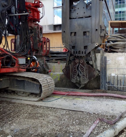


Figure 8: Poor backfill & removal of obstructions during diaphragm walling resulting in large overbreak and preferential concrete flow outside cage.
The diaphragm wall below this was generally of good quality and built within tolerances as can be seen in figure 9 demonstrating that the diaphragm wall processes adopted were effective. However, these have been undermined by the combination of reinforcement congestion and concrete pour duration.

Figure 9: Exposed diaphragm wall 17m and corner panel (joint offset = 60mm)

CONCLUSIONS
The diaphragm walling process has been used for over 50 years and the technology has developed significantly over this time. In the last couple of years state of the art digging technologies have been deployed to NZ that have enabled the delivery of two challenging projects that would have otherwise not been possible. The HC05 worked effectively in restricted headroom and the LRB155+XS2 on a small restricted site; both demonstrated the suitability of the hydrofraise digging technology in Auckland soils and ECBF rock.
Other aspects of the diaphragm walling process such as support fluids and tremie concrete have seen significant research and development in response to the changes in the nature and availability of materials. Specifications and guidance documents have been published by internationally renowned organisations such as the ICE, EFFC and DFI to disseminate this information. One project demonstrated that, even with good planning, unforeseen changes and several factors can combine resulting in a poor quality; such issues are likely to be avoided if all parties commit to international best practice guidance.
REFERENCES
European Federation of Foundation Contractors / Deep Foundations Institute (2nd Edition) 2018 Guide to tremie concrete for deep foundations EFFC/DFI Concrete Task Force
European Federation of Foundation Contractors / Deep Foundations Institute (1st Edition) 2019 Guide to support fluids for deep foundations EFFC/DFI Support Fluid Task Force
Institution of Civil Engineers (3rd Edition) 2017 Specification for piles and embedded retaining walls ICE Publishing: London
Wharmby et al 2001 Stormwater tank construction at Blackpool Proceedings of Underground Construction Conference BGS-BTS: London