
Sensitive pyroclastic soils in the Bay of Plenty, New Zealand: microstructure to failure mechanisms
Abstract
Sensitive soils derived from weathered rhyolitic pyroclastic materials are associated with many landslides in the Bay of Plenty. Undrained, consolidated static triaxial tests show contractive p’-q’ plots, strain-softening stress-strain behaviour coupled with rising pore water pressures, shear band formation after peak strength, and considerable strain softening. Cyclic triaxial tests confirm brittle failure and extensive softening of the soil. Pore pressure gradients developed during shearing initiate collapse of clay microstructures into shear zones; further excess pore pressure generation in the shear zone leads to progressive failure. Halloysite, a low-activity clay mineral, is associated with sensitive layers within the pyroclastic sequences. Mushroom cap–shaped spheroidal halloysite results in weak short-range interactions between exposed clay surfaces on incomplete spheroids. This weak bonding allows disassociation of clay aggregates during slope failure, leading to strain softening and the development of flow post-failure.
1 INTRODUCTION
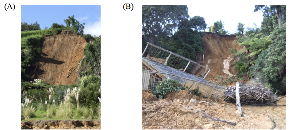
Overnight on 5/6 April 2017 Omokoroa Peninsula in Tauranga Harbour experienced a major landslide event along the coastal cliff margins following the passage of extratropical Cyclone Debbie during the night of 4/5 April. A second large rainfall event, extratropical Cyclone Cook, followed 9 days later on the evening of the 14th April, resulting in a further series of landslides. Altogether, some 18 landslides, many of which comprise complex zones of multiple failures, occurred in two distinct phases (5/6 and 14 April). These landslides clearly cluster into two distinct types (Figure 1): translational slides that extend the full height of the cliffs and denude a considerable length of the cliff face, but only extend a few metres back into the cliff; and flow-slides based in sensitive (ratio of undisturbed/remoulded strength > 4) soil layers that are often well above the mean sea level and which extend up to tens of metres back into the face. The geomorphology shows that these sensitive soil failures are common on the Omokoroa peninsula, and indeed in other parts of Tauranga and the wider Bay of Plenty. We have been undertaking research on the nature and causes of sensitivity in these materials for some time. This paper presents a synthesis of our current understanding of these soils and their behaviour.
Figure 1: Translational (A) and flow-slide (B) landslides initiated following the passage of Cyclone Debbie on 4/5 April 2017. Although translational failures can denude large areas of the slope, flow-slides cause greater excursion into the slope and hence pose greater risk.
2 STUDY SITE
While we have examined and sampled several sites around Tauranga, the data presented here are derived from a landslide at Bramley Drive, Omokoroa. This landslide is situated on the coastal margin of Omokoroa Peninsula approximately 12 km north of Tauranga City. The coastal bluffs at the site are 33 m above high tide, and the landslide debris protrudes onto the intertidal sand flats. The initial failures occurred in early August 1979 and resulted in ~ 30 m retreat of the cliff over a length along the cliffs of ~ 60 m; a distinctive ledge was apparent in the failure at approximately 24 m below the original ground surface, and the debris flowed rapidly to a distance some 150 m from the cliff (Gulliver and Houghton, 1980). The scarp remained essentially stable for just over 30 years until 2011 and 2012 when several smaller reactivations resulted in a further ~ 10 m retreat. A steep (50 – 60°) scarp some 24 m high is now exposed, along with an eroded debris zone approximately 130 m in extent.
Three key sequences of material are exposed in the landslide scarp (Kluger et al., 2017): recent eruptives including the Rotoehu Ash (~ 50,000 years) and younger materials with the modern soil developed on late Quaternary tephras; the rhyolitic Hamilton Ash sequence (~0.05 – 0.35 Ma) derived from Taupo Volcanic Zone eruptives; and the Pahoia Tephras (0.35 – 2.18 Ma). The Pahoia Tephras are a complex unit within the wider Matua Subgroup. Whilst some layers are definitely tephra-fall deposits, the unit contains many reworked, weakly-consolidated pyroclastic materials of rhyolitic origin as well as partially to non-welded pyroclastic flow deposits (ignimbrites); it is this Pahoia Tephra sequence that contains the sensitive soils associated with landsliding throughout the Tauranga region.
3 HALLOYSITE
We have identified halloysite as the key clay mineral in the pyroclastic sequence comprising the Pahoia Tephra sequence in the Bay of Plenty (Kluger et al., 2017). Halloysite is a product of weathering mainly of volcanic glass (± plagioclase feldspars) in an environment with abundant Si in the pore water. In particular, in high-Si rhyolitic eruption products, such as the ignimbrites and tephra-fall beds derived from eruptions in the Taupo Volcanic Zone, especially under conditions of impeded drainage, halloysite is a common alteration product. Halloysite is a 1:1 kaolin-subgroup clay mineral with one silanol sheet for each aluminol sheet. This structure is similar to that of kaolinite but halloysite contains additional interlayer H2O (water).
Halloysite-rich soils formed in weathered tephras characteristically have very low bulk densities and associated high porosities (Table 1). Many authors report small pore spaces, and natural moisture contents are high as the soils remain close to fully saturated in normal field conditions due to the capillary effects of small pores. Liquid and plastic limits tend to be relatively high, yet conversely, plasticity indexes are low: halloysite-rich soils typically plot below, but parallel to, the A-line as “high compressibility silts” (Wesley, 1973). High limit values are to be expected from the H2O molecules included in the structural formula for hydrated halloysite, but the low plasticity indicates that the water is in positions that does not lubricate contacts between clay minerals or enhance chemical and electrostatic surface interactions. Thus the low plasticity is a reflection of the relatively low cation exchange capacity (CEC) of halloysite, and is reflected in a low activity. Despite a low activity (shrink/swell capacity) halloysite minerals can dehydrate, resulting in shrinkage. This dehydration is irreversible under ambient environmental conditions, and hence swelling is unlikely to be a problem. Low plasticity index and very high field moisture contents leads to characteristically very high liquidity indexes.
Table 1: Ranges of physical properties of halloysite-rich soils (after Moon, 2016).
| parameter | symbol | unit | range |
| dry bulk density | dry | kg m-3 | 480-1080 |
| porosity | | % | 33-71 |
| field moisture content | wfield | % | 31-160 |
| saturation | % | 91-109 | |
| coefficient of permeability | k | *10-9 ms-1 | 1-111 |
| plastic limit | PL | % | 18-75 |
| liquid limit | LL | % | 34-110 |
| plasticity index | PI | % | 10-48 |
| liquidity index | LI | 0.3-2.4 | |
| peak cohesion | c, c’ | kN m-2 | 0-70 |
| peak friction angle | , ’ | ° | 21-56 |
| residual cohesion | c, c’ | kN m-2 | 0-13 |
| residual friction angle | , ’ | ° | 9-34.2 |
| sensitivity | St | 5-140 |
Strength parameters for undisturbed samples show characteristically low cohesion, reflecting the low CEC, but high friction angles which are generally attributed to irregular morphologies of halloysite clay minerals. Typical values of residual cohesion are very low, whereas the residual friction angle ranges from 15 to 35°. Thus, relatively high friction angles may be retained after remoulding. This is not always the case however, and in some instances considerable loss in frictional resistance is observed. As these halloysite-rich soils have formed in situ without any previously elevated overburden stresses, they remain normally consolidated.
The morphology of halloysite clays is highly variable, and the interactions between clay mineral surfaces are strongly influenced by the morphology. Typically, halloysite crystals are considered to be tubular: a mismatch between the sizes of the silanol and aluminol sheets that is exacerbated by interlayer water which weakens inter-layer forces, allows rolling of clay layers. This characteristic is the subject of considerable research into halloysite nanoparticles as vectors for drug delivery or as components in polymers. However, it has long been recognised that halloysite also occurs in other forms, in particular small spheres. Smalley et al. (1980) recognised spherical halloysite as a key component of the sensitive soils at the base of the landslide at Bramley Drive, and suggested that limited particle interactions across the surfaces of the spheres contributed to the sensitivity of the materials.
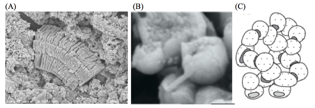
Recently we have recognised two more morphologies of halloysite in Bay of Plenty sensitive soils: books (Cunningham et al., 2016) and mushroom-caps (Kluger et al., 2017). The book morphology (Figure 2A) mimics a common morphology of kaolinite, and may have been responsible for mis-identification of halloysite clays in the Bay of Plenty in previous work. The mushroom-cap morphology (Figure 2B) is recognised from the same location at Bramley Drive as the spheres described by Smalley et al. (1980). With improved SEM technology, we identify these spheres as incomplete: individual halloysite spheroids are typically ~250–400 nm in diameter with openings ~80–160 nm in diameter on one side, giving the “mushroom-cap” appearance. We infer that the spheroids observed are composed of concentrically stacked 1:1 layers, reminiscent of the structure of an onion. A complete silanol layer, as comprises the outer sphere surface, carries a net negative charge. In the openings, ends of both silanol and aluminol sheets are exposed, giving a neutral or weakly positive overall charge. Electrostatic or van der Waals forces lead to attraction between the negatively charged convex surfaces of the silanol sheets and the weak positive charges of the concave openings, allowing the individual minerals to aggregate into a network of connected particles in the undisturbed state (Figure 2C). The attractions are short-range however, and detachment by remoulding allows a disaggregation, giving the material a low remoulded strength. While the various halloysite morphologies occur mixed throughout the profile; the mushroom-caps are most abundant in the highly sensitive layers, whereas tubular halloysite is more abundant in the upper, less sensitive materials.
Figure 2: Scanning electron micrographs of (A) book and (B) mushroom-cap morphologies of halloysite. (C) Inferred framework network of mushroom cap clay minerals. Image credits: (A) Helen Turner, (B) and (C) from Kluger et al. (2017).
4 STATIC RESPONSE
Undrained effective triaxial tests were undertaken on samples collected from a sensitive layer near the base of the landslide scarp at Bramley Drive (Mills and Moon, 2016). Tests were undertaken on three 48 mm diameter thin-walled core samples collected from a horizontal bench dug into the headwall of the landslide at a depth of 19 m below the original ground level. The bench was dug out to 1.5 m behind the exposed headwall so that samples were beyond the depth affected by surface weathering effects. Cores were wrapped for transport and storage, and the samples were stored in their tubes in sealed chambers until immediately before testing. Testing followed standard NZ procedures (NZS4402 (1986)), with the exception of the rate of stress application where a high rate of 0.5 mm min-1 was chosen following the model of Gylland et al. (2013). B values greater than 95 % were achieved during saturation, and isotropic consolidation stresses of 140–340 kN m-2 were applied to bracket field overburden stresses. Test results are summarised in Table 2 and plotted in Figure 3.
Table 2: Triaxial test parameters for three core samples from Bramley Drive (after Mills and Moon, 2016)
| parameter | symbol | unit | S1 | S2 | S3 | strength
parameters |
| effective confining stress | c | kN m-2 | 140 | 240 | 340 | |
| saturation parameter | B | % | 95 | 98 | 98 | |
| axial strain at failure | f | % | 1.9 | 3.2 | 2.0 | |
| deviator stress at failure | qr | kN m-2 | 179 | 246 | 299 | |
| strain softening | % | 14 | 20 | 50 | ||
| failure mechanism | W | S | S-W | |||
| peak effective cohesion | c’p | kN m-2 | 26 | |||
| residual effective cohesion | c’r | kN m-2 | 24 | |||
| peak effective friction angle | ’p | ° | 31 | |||
| residual effective friction angle | ’r | ° | 26 |
Figure 3: (A) Deviator stress versus axial strain, and (B) effective stress path plots for static triaxial tests (from Mills and Moon, 2016)
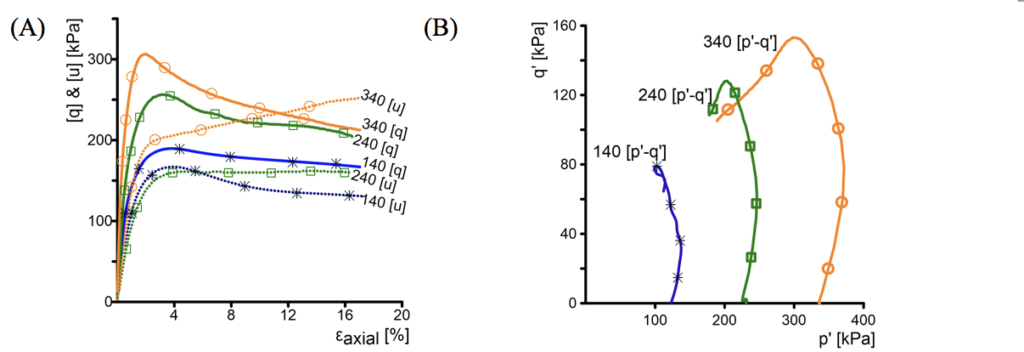
Samples failed at axial strains of 3.2 % or less, and exhibited significant strain softening post-failure as expected for sensitive soils. Pore water pressures climbed sharply on application of axial stress, then dropped or plateaued post-failure in the samples tested at lower effective confining stresses (c = 140 & 240 kN m-2), but continued to increase after failure in the sample at the highest confining stress (c = 340 kN m-2). Effective stress path plots show contractive behaviour, particularly at the higher confining stresses.
Strength parameters derived from these tests are included in Table 2. The values are in keeping with commonly reported values for the strength of halloysite-rich soils (Table 1) and show relatively low cohesion and high friction angle in undisturbed (peak) conditions. Residual cohesion is similar to the undisturbed value, and the friction angle undergoes only a small change post-failure. Strain softening of effective cohesion values and friction angles is thus limited, indicating that pore water pressure changes post-failure are key to the significant strain softening observed.
Following strength testing, thin section description and computerised x-ray tomography (CT) of the failed cores were undertaken to examine the fracture surfaces developed during stress application. Thin sections were prepared by cutting surfaces oriented vertically on the failed core; these were air-dried slowly under ambient laboratory conditions, and impregnated with resin before following normal thin section preparation procedures. Small (10 mm inside diameter) core samples were taken normal to the macroscopic shear surface for micro-CT scans which were undertaken using a Bruker Skyscan 2000 Micro-CT at the University of Auckland.
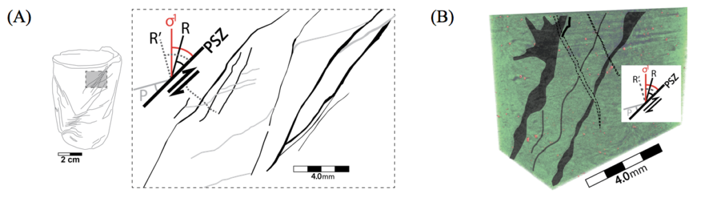
Thin section samples (tested at 240 and 340 kN m-2) show multiple principal shear zones evidenced by zones of particle reorientation up to 1.0 mm wide that have distinct boundaries with the surrounding matrix material (Figure 4A). The shear zones are continuous across the full length of the thin sections, and commonly show branching and coalescence, most notably around weathered zones or particle concentrations. As well, minor shears that are not continuous are commonly observed. A portion of the micro-CT scan image (sample tested at 355 kN m-2 effective stress) is shown in Figure 4B. A matrix of clays is indicated in green, dense particles are red colours, and shear zones are highlighted with pale green, black and pink annotations. All angles are measured with respect to the angle of the macroscopic principal shear (PDS) identified on the failed core. Two small shear zones 0.05–0.1 mm thick and spaced 2–3 mm apart are apparent in the core. These are most closely oriented to the direction expected for Reidel R shears, and are linked by antithetic R’ shears. Reorientation of particles within these shear zones is not apparent, but the clay matrix within the shears is notably denser than in the surrounding matrix.
Overall, we observe brittle failure occurring along multiple shear zones oriented approximately as expected for Riedel shears, with some antithetic (R’) shears observed linking the principal shear zones. Clay minerals are densified in the shear zones compared with the matrix density, and larger grains are reoriented to parallel the shear zone.
Figure 4: Thin section (A) and microCT section (B) of failure surfaces (from Mills, 2016).
5 CYCLIC RESPONSE
Cyclic triaxial testing on samples from the same location as those used for the static testing was undertaken at Bremen University, Germany. Thin-walled samplers of 36 mm internal diameter were pushed into the sampling platform; samples were wrapped and shipped to Germany in their samplers. Cyclic testing was undertaken following DIN 18137-2:2011-04 (2011). Samples were isotropically consolidated to 240 kN m-2 effective stress to match the estimated in situ consolidation stress at 19 m depth. After consolidation a combination of average shear stress (av) and cyclic shear stress (cyc) was applied in order to assess the combined effects of static and cyclic loads on the shear strain development and shear strength.
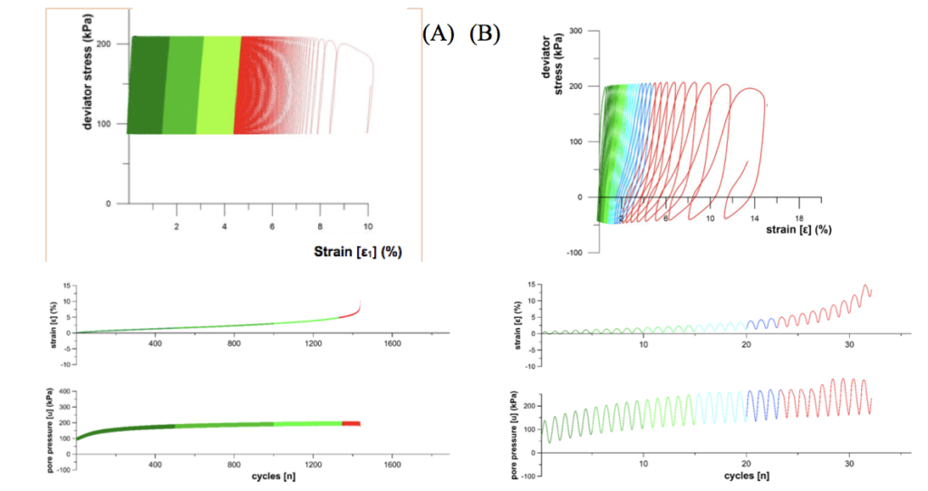
Figure 5A shows the test results for one sample tested at with high average shear stress of av=75 kN m-2 and low cyclic shear stress of cyc=30 kN m-2, meaning that the sample remains in compression throughout the test. Notable is that the hysteresis loops remain relatively unaffected by loading cycles for most of the test, then the sample fails suddenly over a few cycles (failure in this case is defined as 5 % single amplitude axial strain). Pore water pressure rises sharply as the stress is initially increased, then remains high throughout the test. By contrast, Figure 5B shows the results of a test run with average shear stress of av=40 kN m-2 and cyclic stress of cyc=60 kN m-2 (ie. the sample experienced extension for part of each loading cycle). Both samples described develop compressional strain and increased pore water pressure throughout, but in the second test the hysteresis loops develop a much more distorted shape (decreased stiffness), especially in the extensional regime, as the sample approaches failure; post-failure the pore water pressure increases and the stiffness decreases markedly.
The sudden increase in axial strain and the decrease in stiffness observed in the cyclic triaxial tests is in keeping with the sensitive nature of the soils where brittle failure and considerable post-failure strain softening are observed in the static compression testing presented above. The development of pore water pressure during loading is inferred to play a significant role in the development of failure in these materials
Figure 5: Cyclic triaxial test results for two samples. (A) 75 kN m-2 average applied stress, 30 kN m-2 cyclic stress; (B) 40 kN m-2 applied average stress, 60 kN m-2 cyclic stress (from Mills, 2016)
6 CONCLUSION
Sensitive soils have been known to pose a landslide hazard at Omokoroa and in the wider Bay of Plenty for some time. These sensitive soils create flow-slides with long runout, and failures that regress back into the slope over long time intervals. Recognition of halloysite as the key clay mineral in the Pahoia Tephra sequence that hosts the failure surface of these flow-slides allows us to predict and understand the basic physical characteristics of the soils; most notably inactive clay minerals with high liquidity indexes which are characteristic features of sensitive soils globally. Remoulded halloysite samples are also known to have distinctive responses to pH, and cation type and concentration (Theng and Wells, 1995). These responses allow for the possibility of slope improvement by means of cation manipulation, an avenue being investigated by Robertson et al. (this volume), but any treatment needs to be targeted to known characteristics of halloysite.
In static strength testing the materials exhibit brittle failure at ~ 3 % strain with well developed principal shear surfaces showing a densified clay mineral matrix and particle realignment. A contractive response is exemplified by considerable strain softening after failure, and pore water pressures that rise sharply with applied stress and remain high post-failure. Cyclic strength testing indicates considerable resistance to cyclic stresses, but when failure does occur it happens very suddenly, with samples exhibiting complete breakdown over a small number of loading cycles, a reflection of the sensitivity of the soil.
By looking more deeply at the structure of the clay minerals, identifying mushroom-cap shaped halloysite spheroids as dominant in the most sensitive soil layers allows us to recognise the nature of the framework of the soil, and hence infer mechanisms for breakdown of the structure. Little cohesion or friction softening is recognised in static triaxial testing; this follows from the nature of the clay minerals – spheres will not inherently realign as might be expected with platy minerals, their friction will be similar before and after; cohesion will presumably be lost, but limited cohesion exists in the undisturbed condition due to only weak attractive forces being able to develop between the outer and broken segments of the mushroom caps. We infer that excess pore pressure gradients initiate the separation of mushroom caps, leading to brittle shear surface evolution. Dramatic particle rearrangement on detachment of the weakly bonded spheroids leads to release of further pore water along the shear zone, enhancing pressure gradients and hence propagation of failure progressively to form discrete shear surfaces.
7 ACKNOWLEDGEMENTS
We thank Deutsche Forschungsgemeinschaft (DFG) via the Integrated Coastal Zone and Shelf Sea Research Training Group INTERCOAST for funding, and for scholarship support for MOK, Callaghan Innovation, the University of Waikato, and MBIE for scholarship support for PRM. Helen Turner at the University of Waikato and Dane Gerneke at the University of Auckland are thanked for SEM imaging and microCT scanning.
REFERENCES
Cunningham, M.J., Lowe, D.J., Wyatt, J.B., Moon, V.G., Churchman, G.J. (2016). Discovery of halloysite books in altered silicic Quaternary tephras, northern New Zealand. Clay Minerals 51, 351-372
Gulliver C. P. & Houghton B. F. (1980). Omokoroa Point land stability investigation. Report prepared by Tonkin & Taylor for Tauranga County Council (New Zealand).
Gylland, A. S., H. Rueslåtten, H. P. Jostad,. S. Nordal. (2013). Microstructural observations of shear zones in sensitive clay. Engineering Geology 163: 75-88.
Kluger, M. O., Moon, V. G., Kreiter, S., Lowe, D. J., Churchman, G., Hepp, D. A., Seibel, D., Jorat, M. E. & Mörz, T. 2017. A new attraction-detachment model for explaining flow sliding in clay-rich tephras. Geology, 42, 131-134.
Mills, P. R. (2016). Failure mechanisms in sensitive volcanic soils in the Tauranga Region, New Zealand. Unpublished MSc thesis, University of Waikato.
Mills, P. & Moon, V. (2016). Static failure mechanisms in sensitive volcanic soils in the Tauranga Region, New Zealand. In: Neeson, F. C., Lacey, D., Buxton, D. & Storie, L., eds. 11th Australia and New Zealand Young Geotechnical Professionals Conference, 2016 Queenstown, New Zealand. New Zealand Geotechnical Society.
Moon, V. (2016). Halloysite behaving badly: geomechanics and slope behaviour of halloysite-rich soils. Clay minerals, 51(3), 517-528.
Robertson, T., Moon, V. G., Lowe, D. J. (this volume). Is there a potassium-based solution to sensitive soil slipping within the Bay of Plenty?
Smalley L. J., Ross C. W. & Whitton J. S., 1980. Clays from New Zealand support the inactive particle theory of soil sensitivity. Nature, 288, 576−577.
Theng B. K. G. & Wells N., 1995. The flow characteristics of halloysite suspensions. Clay Minerals, 30, 99-106.
Wesley L. 1973. Some basic engineering properties of halloysite and allophane clays in Java, Indonesia. Géotechnique, 23, 471−494.