
Pre-excavation grouting for groundwater ingress control in tunnelling – Auckland, New Zealand.
Abstract
Water ingress into a mined tunnel can be an issue – not just for construction but also for depressurisation and the potential consequential surface settlement. The Waterview Connection in Auckland has twin ~14.5m diameter TBM tunnels linked by 16 mined cross passages. Each cross passage is under 15m long, placed at ± 150m centres en route with excavation works predominantly through the East Coast Bay Formation geology.
Based on geotechnical investigations and probe hole drilling, some cross passages were known to have a high risk of strong water ingress. Furthermore, the TBM passage in the first tunnel had encountered zones where Earth Pressure Balance (EPB) methodology was essential to limit groundwater inflows which would otherwise have exceeded permitted limits. These limits addressed the risks associated with drawdown and settlement effects at the surface, and the risk of hydraulic connection to the Oakley Creek where it crossed the alignment.
This paper outlines the unique challenges and design for dealing with high groundwater inflow in the East Coast Bays Formation, the construction methodology used in a segmental lined tunnel and efficacy of the pre excavation grouting used where necessary in some of the cross passages. An effective seal was achieved through the pre-excavation permeation grouting.
1 BACKGROUND INFORMATION
The Waterview Connection is a New Zealand Transport Authority (NZTA) motorway construction project that completes the Auckland western ring route linking State Highway (SH) 20 to SH16 by way of a 3 lane dual carriageway motorway in Auckland, New Zealand. The project includes a tunnel section consisting of 2 tunnels, 2.4 kilometres long running in a north south direction (Figure 1).
Figure 1: Map of Auckland with the new Waterview Connection route.
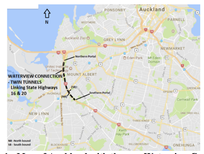
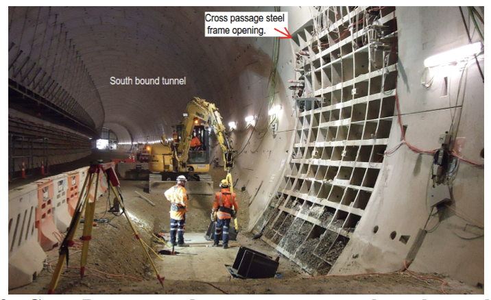
The tunnels are connected by sixteen mined cross passages, each having an internal span of 5.2m and being 6.0m in height. At each of the cross passage entrances, concrete segments were replaced with steel segments to form a steel frame after opening (Figure 2).
Figure 2: Cross Passage steel segment entrance along the south bound tunnel.
The mainline tunnels and cross passages were designed as undrained structures to prevent groundwater drawdown in the permanent condition. The tunnel alignment passes under areas of residential and commercial land including a live rail track and petrol station at the surface roughly 30m-40m above the crown. This undrained approach, preventing groundwater drawdown, was used to reduce the possible consequential surface settlement and associated damage to these sensitivities.
Prior to commencement of the cross passage excavation works, observations and investigation testing identified some of the cross passages were likely to encounter high groundwater inflows of greater than 20l/sec that could, if not controlled, result in groundwater drawdown. One of the key objectives of the pre excavation grouting was to maintain the undrained condition during cross passage construction. It was important to be able to control flows during construction not only to manage drawdown impacts but also for the safety of the crew executing out the excavation works.
2 GEOLOGY/HYDROLOGY
The project site is located within the Waitemata basin where the geology generally comprises of a thick sequence of interbedded extremely weak to weak siltstones and sandstones (East Coast Bays Formation (ECBF)) and locally interbedded coarser grained volcaniclastic sandstones (Parnell Grit Member) which are part of the Waitemata Group.
After an extensive borehole investigation prior to construction commencing, the geotechnical information revealed the Waterview tunnel alignment was positioned to drive through the ECBF and the Parnell Grit member sequence that had undergone faulting and folding during the tectonic uplift of the Waitemata basin (Figure 3). The presence of the faults crossing the proposed alignment are generally discrete zones of displacement rather than large zones of fractured rock. This embedded sequence is typical within the Auckland city geology.
Figure 3: Geological long section (Southbound tunnel)

The groundwater levels measured along the alignment were typical of the regional groundwater table, typically falling from RL 42m near the southern portal and discharging towards the harbour in the north at a gradient of around 4% and locally discharging to Oakley Creek (see Figure 3). Ground water flows through the Waitemata Group rock are dominantly defect controlled through fractures and bedding planes. Minor flow can be expected through the matrix of coarser sandstone beds (Parnell Grit member).
During the design stage, the majority of cross passages were thought to be excavated through “typical”, low hydraulic conductivity rock (Kh =3 x 10⁻⁷ m/s) with low storativity. Analyses indicated inflows were likely to be negligible (<1 l/s when the entire cross passage is open and dewatered).
In the tunnel section between cross passages XP11 and XP14, higher strength coarser grained rock (higher percentages of Parnell Grit) was intercepted, resulting in an increased overall hydraulic conductivity (Kh = 10-5 m/s).
Pumping tests within this area indicated sustained discharges of 5 l/s and peak discharges of up to 20 l/s may be possible during excavation. The design assessment indicated such flows were likely to cause drawdown and possibly consolidation settlement at the ground surface and therefore pre excavation grouting would be required.
3 CROSS PASSAGE INVESTIGATION
3.1 First tunnel
An initial summary of ground conditions and groundwater behaviors was compiled from the first tunnel. This summary included rock permeability and likely groundwater inflow conditions as the TBM passed each cross passage. The initial summary is provided in Table 1 below.
Table 1: Summary of ground conditions encountered from the first tunnel (Southbound)
| Permeability/Inflow | Cross Passage (XP) | Ground Conditions | Additional Notes: |
| Very low to low permeability (<5L/s)
from discrete fractures |
2, 3, 4, 5,
6, 7, 8, 9, 15, 16, 17 |
Very weak to weak sandstone with thin interbedded siltstone beds. Beds typically 0.5m to 2m thick. UCS of 5 (MPa).
XP16 & encountered extremely weak to very weak sandstone. |
Drawdowns noted in response to various TBM operations, minor to negligible inflows. XP8 – possibility of discrete fracture flows. |
| Moderate permeability
(5 – 10 L/s) |
10, 11, 14 | Very weak to weak sandstone with interbedded siltstone beds (0.3 – 3m thick), UCS 1-20 (MPa). | XP10 – fault logged in face during cutter head intervention with minor inflows noted. Moderate to high inflows possible. Likely to encounter higher percentage of Parnell Grit. |
| High permeability inflows (>30l/s) | 12, 13 | XP12 – Weak siltstone massive with closely spaced joints. UCS of 5 (MPa).
XP13 – Weak coarse grained sandstone interbedded with Parnell Grit. Beds typically 1m to 2m thick. UCS 5-25 (MPa). |
Likely to dewater and recover quickly but pumped volumes will remain high throughout drained period. Cutter-head intervention (6m south XP12) was abandoned due to face instability. |
This initial summary of ground conditions encountered during the construction of the first tunnel, showed cross passages XP12 and XP13 would likely require groundwater control with the possibility of further ground treatment at cross passages XP10, XP11 and XP14.
3.2 Probe drilling
Probe drilling was used to verify and assess the geological and hydrogeological conditions ahead of each cross passage excavation. After completion of the first (southbound) tunnel, probe holes were drilled through the steel openings at each cross passage.
The probe drilling investigation completed at least 2 probe holes at each cross passage, and ground class, support type for construction and groundwater inflow measurements were investigated and reported.
Drilling was carried out using a horizontal rotary drill rig to a length of 10m. The core was logged and groundwater inflow measurements were taken during and 24 hours after drilling completion. Figure 4 presents the monitoring results from the inflows recorded during probe hole drilling.
Figure 4: Summary of Groundwater Inflows from Probe Drilling

The groundwater inflow results identified cross passages XP08, X10, XP11, and XP12 required pre-excavation grouting due to groundwater inflows exceeding the allowable threshold of 27 l/min sustained flow after 24 hours from a 10m probe hole.
Further analysis of the results was undertaken by the project’s hydrogeologist using the analytical method of Heuer (1995). The analysis calculated a rock mass permeability of between 5 x 10⁻⁷ m/s for XP 8 and 1 x 10⁻⁵ m/s for XP11 and XP12. The estimated peak inflow range during excavation was calculated to be of between 5-10 l/sec for XP 08 and up to 50 – 80 l/sec for cross passages XP11 and XP12.
Further monitoring of groundwater flows was undertaken during the canopy installation. The canopy tubes were installed around the crown of the cross passage in a semicircular profile, then grouted. Between the time of the install and grouting, high groundwater inflows were observed, similar to the high flows measured from the probe drilling. Cross passage XP12 had some of the highest flows (>20 l/sec) until the canopy tube was either capped or grouted.
4 GROUTING DESIGN AND METHODOLOGY
Pre-excavation grouting was seen as a necessary method of reducing inflows for cross passages XP8, 10, 11 and 12. The main objective was reducing inflows to levels below resource consent levels i.e less than 27 l/min per 10m length of probe hole sustained over 24 hours.
4.1 Drilling
The pre excavation grouting involved drilling horizontal boreholes (65mm in diameter) slightly inclined to avoid overlap and to maximise the area grouted.
4.1.1 Drilling Sequence
The typical arrangement of grout holes is shown in Figure 5. The grout holes were divided into 3 categories:
Primary holes – The primary holes (typically 10 holes) were drilled through 70mm ports which already existed in the main tunnel concrete lining segments for further grouting purposes related to the mainline tunnel lining.
Secondary holes – The secondary holes (typically 11 holes but additional holes were drilled for cross passage XP12) were drilled around the steel opening perimeter through either 100mm diameter steel nipples or through existing port holes in the steel cross passage segments.
Tertiary holes – The tertiary holes (9 x 240mm diameter steel nipples installed in the cross passage opening segments) were initially drilled as test holes to measure groundwater inflows after completion of the initial grouting works. These holes were the final group to be grouted unless the previous holes grouted (i.e. primary holes) had provided sufficient reduction in water ingress.
All drilling and grouting works were completed from the south bound tunnel. A 300mm exclusion zone from the north bound tunnel and a 50 drill deviation was designed to minimise the risk of borehole and tunnel intersections.
The drill rig consisted of a compressed air operated drill with a minimum working pressure of 100 psi and flow volume of 350 cfm. The drill mast was mounted onto an excavator with an elevated platform for access. The boreholes were drilled using a drag bit with water as the flushing medium. As excessive groundwater was expected, allowance was made for an air operated diaphragm pump.
Once drilled, each hole had a valve installed that was kept closed unless flow measurements were to be taken.

Figure 5: Typical arrangement of grout holes at Cross Passages XP11 & XP12. (No secondary holes were drilled for XP08 & XP10.)
4.2 GROUTING
4.2.1 Grouting Material
The cement used for injection grouting was required to meet the requirements of AS 3972 – 1997 for Type GP cement. An initial series of tests were performed on the grout prior to its use for pressure grouting in the holes. Grout properties monitored using a bleed test, with a maximum bleed at 90 minutes of 2%, density test (mud balance) and viscosity test (marsh flow cone test).
A high early strength (HE) cement with grout aid and super plasticiser mix was used.
4.2.2 Grouting equipment
Equipment for the cement grouting was specified to include:
- High speed colloidal grout mixer capable of mixing grouts with water/cement (w/c) ratios between 0.3 – 3.0.
- Grout agitator capable of keeping grout at ratios between 0.3 and 3.0 in suspension.
- Grout pump – capable of pumping at a range of 10 – 30 l/min reducing to 0 – 2 l/min at PMax. A valve type pump (piston pump) was used.
- Flow meter and pressure gauges for air, water and grout supply lines, packers and fittings to supply a continuous flow of grout and an accurate pressure control.
4.3 Initial Trial
Prior to any grout testing procedure at each of the targeted cross passages, strain gauges were installed on mounting blocks welded onto the cross passage openings. Convergence prisms were set up for convergence monitoring of the tunnel lining.
Under the Standard Operating Procedure as part of the design requirements, a water pressure test to stimulate grouting pressures on the tunnel lining was attempted in a drilled tertiary hole (T1) at XP12. This trial was abandoned due to the sub-contractor being unable to increase or even reach pressure as the water pumped through the hole kept dissipating into the ground resulting in no pressure build up. The trial test was then continued with grout consisting of a 1.5 w/c ratio and no additives.
The drilled hole for the trial was 11.4m in length with a 50 inclination through the steel segment of the cross passage opening. The drill hole is stopped 200mm from the north bound tunnel to determine the full effect of the grouting method and maximum pressure limits.
The hole was then plugged with an inflated packer at the opening. Pressure grouting initially commenced to an average pressure of 5 bar with a grout take of 50 litres. As the grouting progressed the pressure was increased by 1 bar increments as 0.5 bar increments were not possible with the design of the piston pump.
During testing, the pressure was increased to 6 bar and then up to an average 7 bar (max 8.5 bar) with grout takes of 40 and 15 litres respectively. The test was stopped at this point, based on the total volume of grout being equal to three times the hole volume. Immediately after testing, the hole was flushed with water with the surrounding holes left open.
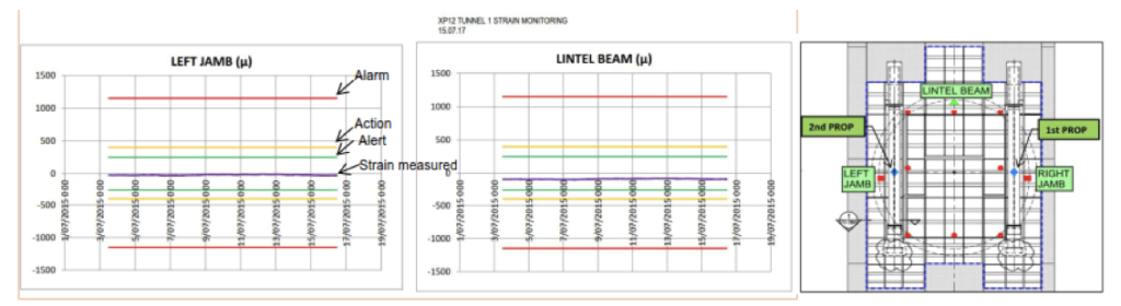
The results of the strain gauges and convergence monitoring were assessed throughout the full trial to determine if any significant strain was induced in the tunnel lining. Grouting pressures were maintained during the trial in 10 min pressure increments, as best the pump could provide for. This allowed the data logger of the strain gauges to update in a 5 min cycle. At the end of the trial the monitoring observed very minimal to no movement from all gauges (Figure 6) and prisms. This allowed grouting to proceed, beginning with XP12, with daily convergence, strain gauge, and surface monitoring ongoing.
Figure 6: Strain gauge monitoring on the tunnel lining during the grout trial.
4.4 Cross Passage Grouting Sequence
The primary holes of XP12 were initially drilled and grouted. During grouting, nearby holes were monitored for interconnections and pressure release. Even with the slight incline, some of the nearby holes interconnected. After completion of the primary grouting, several of the tertiary holes were drilled and the inflow measured. These measurements gave an indication of whether further grouting was necessary.
In all the targeted cross passages, both the primary and tertiary holes were grouted. Additional holes around the steel opening (secondary holes) were drilled and grouted at XP11 and 12 prior to proceeding to the tertiary holes (within the excavated area).
5 RESULTS OF GROUTING PERFORMANCE
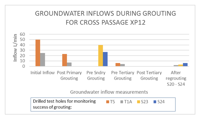
After completion of grouting at each stage (primary, secondary, tertiary) several of the tertiary holes were either uncapped or drilled to measure groundwater inflows. Figure 7 presents the measured inflows from the monitoring holes during grouting procedure as it progressed in towards the excavation zone.
Figure 7: Cross Passage XP12 groundwater inflow measurements at each stage.
During the grouting process, measurements of initial groundwater inflows and subsequent grout volumes were recorded for each hole. The results for cross passages XP10 and XP12 are presented in the following figures.
Figure 8: Initial groundwater inflow and subsequent grout takes for XP12.

Figure 9: Initial groundwater inflow and subsequent grout takes for XP10

The results presented in Figures 8 and 9 generally show large grout takes correlating with high inflows. This also gave the indication there were possible distinct zones, possibly related to highly fractured zones or zones of interbedded Parnell Grit. Where holes measured lower flows but high grout takes there was generally an interconnection with adjacent holes which registered increased pressure very quickly if not instantly.
6 POST GROUTING – CROSS PASSAGE EXCAVATION
Logging during excavation of cross passages XP8, XP10 – XP12 noted the following ground conditions and groundwater inflows:
- Dripping from joints or canopy tubes as excavation progressed. Generally estimated to be less than 5 l/min over the full excavated face (XP8, XP10, XP11, & XP 12).
- XP12, from the first advance, mapping of the excavated face recorded highly fractured massive siltstone, with indistinct bedding. Groundwater inflows were recorded as damp (<5 l/min)
- XP11 encountered a fault zone within approximately the second and third advance. Groundwater inflows were recorded as damp (<1 l/min).
- XP08 and XP10 encountered Parnell Grit with groundwater inflows recorded as damp with minor seepage from crown around the canopy tubes.
7 CONCLUSION
- Groundwater inflows during cross passage excavation were successfully reduced to manageable levels due to the pre-excavation grouting methodology adopted.
- The investigation and observational methods used to determine where pre excavation grouting would be required, was a successful program in itself.
- Grout pressures of up to 8.5 bar were able to successfully infill the joints and fractures with grout, while having no detrimental effects on the mainline tunnel lining.
- Grout pressures and volumes established in the initial trial managed to successfully reduce groundwater inflow volumes during excavation.
- High grout volumes generally correlated to holes measuring high groundwater inflows.
- High inflows recorded at cross passages XP12 and XP11 encountered highly fractured zones during cross passage excavation.
8 ACKNOWLEDGEMENTS
The author gratefully acknowledges the Waterview Well Connected Alliance team, (the designers and the construction team) who put a lot of time and effort into providing the right information and construction knowledge for these works to happen. The support and contributions of Evan Giles and Wataru Okada of WSP are also gratefully acknowledged.
REFERENCES
Bowskill, A. & Harrison, C. (2014) High-pressure Fissure Grouting for Drill and Blast Tunnelling, Ambuklao, Philippines. Proceedings of the 15th Australian Tunnelling conference, 2014. – Underground Space – Solutions for the Future. Sydney, Australia.
Heuer, R.E. (1995) Estimating rock tunnel inflow, Proceedings of the Rapid Excavation and tunnelling Conference, June 18-21, 1995, San Francisco, California.
Houlsby, A.C. (1990) Construction and design of cement grouting – A guide to grouting in rock foundations, John Wiley & Sons, Inc, New York.
Mahajan, R & Okada, W. (2017) Design of Mined Cross Passages for Waterview Project Auckland (NZ): Comparison between Predicted vs Actual Performance. Proceedings of the World Tunnel Congress 2017 – Surface challenges – Underground solutions. Bergen, Norway.
Spies, P., Burden, J. and Hanke, S. 2014. The Waterview Connection Project – Progress to date, Proceedings of the 15th Australian Tunnelling Conference, 2014. – Underground Space – Solutions for the Future. Sydney, Australia.
Warner, J. (2004) Practical handbook of grouting, John Wiley & Sons, Inc, New Jersey