
Abstract
Assessment and mitigation of potential liquefaction is a critical requirement for successful infrastructure design in seismically active regions of New Zealand. This paper highlights several important lessons learnt from the design and construction of ground improvements to mitigate the effects of liquefaction on the MacKays to Peka Peka Expressway. Learnings are presented on the design and construction challenges of implementing four ground improvement techniques: Undercut and replacement, in-situ mixing, vibro-densification, and vibro-replacement with particular reference to improvement of fine, poorly graded dune sands. The findings lead to a number of lessons learnt for the project team, the most significant being that widely adopted, empirically based correlations for ‘improveability’ of sands based on fines content/plasticity and soil behaviour indices, may be unreliable when applied to soils with high uniformity, sphericity and porosity.
1 INTRODUCTION
A new expressway has recently been completed along the Kāpiti Coast near Wellington, New Zealand. The 18km long, four lane MacKays to Peka Peka (M2PP) Expressway was designed and built by an Alliance, made up of Fletcher, Beca, Higgins and the New Zealand Transport Agency (NZTA).
The M2PP Expressway includes fifteen road bridges and three cycle, walkway and bridleway bridges. It forms part of the Wellington Northern Corridor, and opened earlier this year. The Wellington Northern Corridor runs from Levin to Wellington Airport and is one of seven Roads of National Significance (RoNs) that the New Zealand Government has identified as essential state highways that support economic growth. After a major earthquake, the expressway is to form part of a life-line route to provide providing access to the City of Wellington.
2 MATERIALS
2.1 Geological Setting
The expressway route crosses the coastal plain to the west of the Tararua Ranges, in an area that has been shaped by repeated cycles of glaciation that have occurred in the past two million years. Much of the route is underlain by potentially liquefiable dune sands and silts interspersed by peat (Coe & Alexander, 2012). Loose to medium dense Holocene sands and underlying Pleistocene sands are present under most bridge abutments. Ground water was located near surface across much of the 18km long expressway.
3 DESIGN REQUIREMENTS
3.1 Seismic Loading
The lower North Island of New Zealand is a seismically active region, producing large magnitude earthquake events. Although no major active faults are mapped passing directly through the expressway site, the high shaking hazard results in design peak ground accelerations of up to 0.98g in a 1/2500-year ultimate limit state (ULS) design event. Many of the bridge sites were underlain by materials susceptible to widespread liquefaction or cyclic softening under earthquakes of 1 in 100 years and higher.
3.2 Ground Improvement Design Philosophy
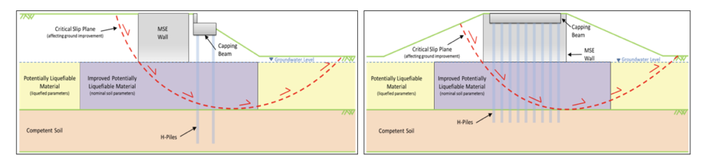
Ground improvement was primarily utilised to control seismically induced displacements of bridge abutments to around 150-200mm under ULS seismic events. These displacements were considered to represent a reasonable limit for the steel H piles that supported the bridge abutments. The extent of the required ground improvement area was determined from seismic slope stability analyses, with typically around 30m x 50m plan area of ground improvement beneath each abutment. A simplified diagram illustrating the analyses undertaken for sizing the ground improvement is presented in Figure 1.
Figure 1: Longitudinal and transverse seismic displacement assessments (not to scale).
4 PRELIMINARY GROUND IMPROVEMENT DESIGN
4.1 Proposed Methods
The selection of ground improvement techniques during the initial design phase was based on anticipated equipment availability, cost and ground conditions. Preliminary design assumed a combination of the following techniques, presented below in order of increasing cost:
- Excavate and replace;
- Vibro-compaction (vibroflot);
- Vibro-replacement (stone columns);
- Insitu soil/cement lattice structures.
4.2 Initial Selection Process
4.2.1 Excavate and Replace
Excavate and replace options were proposed for areas where peat, unsuitable fine-grained soil or shallow zones of liquefiable soil underlay the footprint of bridge abutments. Excavation to depths of up to 5m below the water table were considered. Proposed backfill material comprised either imported hard fill or Holocene dune sand, with the latter being preferred on cost and environmental considerations. Where conventional earthworks compaction techniques were not expected to sufficiently compact the replaced material, such below the water table, vibro-densificaton was proposed.
4.2.2 Vibro-Desification
Vibro-densification was proposed as a method for in-situ improvement of clean sands and sand fill used to backfill undercut areas. Densification was to be validated utilising cone penetration tests (CPTs) undertaken between improvement points. These results were then to be compared against design curves of CPT penetration resistance (qt) versus depth to achieve the desired liquefaction resistance.
4.2.3 Vibro-Replacement
Vibro compacted gravel (stone) columns were proposed as the principal ground improvement method to densify deeper in-situ sand deposits. Based on historical experience and published research, the upper limit for most effective densification was assumed to be a friction ratio of 1.0 or a soil behaviour index (Ic) of approximately 2.0. Column spacing for planning purposes was developed based on the methodology published by Barksdale and Bacchus (1983). Densification was to be validated in the same manner as for vibro-densification, conservatively ignoring the beneficial effects of shear stiffening and improved drainage.
4.2.4 In-situ soil/cement lattice
For ground improvement on sites containing soils that were not anticipated to respond to vibro replacement methods, such as soils containing a significant proportion of fine grained material or plastic interbeds, ground improvement by stress redistribution was proposed. This method improves the resistance of soil through the introduction of stiff elements that limit overall strains to a point where liquefaction is inhibited. The initial lattice design assumed in-situ cement / soil mixed orthogonal panels (or diaphragms), constructed vertically through potentially liquefiable soils at 5m centres each way. The design approach was based on the stress redistribution method as described by Baez & Martin (1994), modified by the recommendations of OTREC (2013) after Ngyugen et al. (2012) to account for strain incompatibility.
5 Ground Improvement trials
5.1 Excavate and Replace with Vibro-Compaction
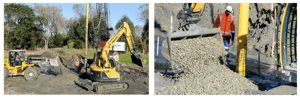
At the Paetawa Drain Bridge, near the northern end of the project, site investigation had identified organic deposits extending down to 5m below the water table. A design was developed that involved excavating the peat and its replacement with compacted sand fill, followed by vibro-compaction of any low density areas. De-watering was not used due to the extensive peat deposits and large area of replacement and high water table. Figure 2 illustrates the typical working conditions.
Figure 2: Excavate and replace at the Paetawa Bridge Site.

CPT testing undertaken following backfill (using only conventional earthworks methods) indicated that further densification was required below the groundwater table and particularly within a continuous zone at the interface between insitu and replaced material.
Vibro compaction field trials were then undertaken on the fill using a range of probe sizes. The field trials demonstrated that regardless of the equipment used, the loose sand fill below the ground water level could not be compacted to meet the design criteria. Site observations indicated that the sand fill introduced from ground level failed to migrate down towards the probe tip, instead remaining in suspension. Post-trial CPTs indicated virtually no improvement below the water table using vibro-densification methods.
Following this unsuccessful trail, vibro-compaction was abandoned. Dynamic compaction was subsequently used to densify the undercut backfill material at the Paetawa Drain Bridge (Robins & Pervan, 2017).
5.2 Vibro-Replacement (Waikanae River Bridge)
The new Waikanae River Bridge was underlain mostly by dense to very dense Pleistocene sand and gravel interbedded with Pleistocene silt. Pre-treatment CPTs identified a 3m to 4m layer of medium dense sands at around 6-8m depth that were potentially liquefiable under ULS Conditions. Vibro-replacement (stone columns) was specified across each abutment footprint area of about 2500m2, to a depth varying between 6m and 8m. The wet, top feed method was selected by the construction team based on the availability of suitable working and water recycling space.
A 25% replacement ratio was initially proposed, based on work by Baez & Martin after Barcsdale and Bacchus, and Priebe. The initial design assumed using a small vibroflot probe to form a 600mm nominal diameter column. This was later changed to a larger probe to assist penetration through the dense upper sand layer, subsequently increasing the nominal column diameter to 800mm.
Figure 3: Photos from the Waikanae River Bridge stone column trials.
A stone (65/40) ballast sourced from the nearby Otaki River was used for the column aggregate construction. Trial areas were setup in a corner of the improvement block for three separate area replacement ratios (21%, 25% and 32%). The results of CPT testing midway between the columns found that the area ratio had to be increased to the maximum trialled area replacement ratio of 32% (1.5m triangular grid pattern) to achieve the required level of densification.
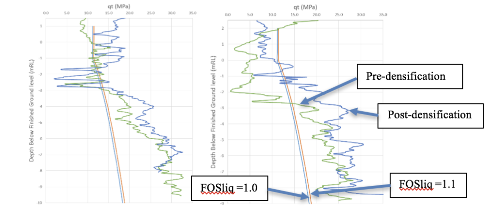
Further interpretation confirmed that the treatment generally resulted in adequate densification to the targeted sand layers. Some variability was present with limited improvement through interbedded silt layers, as well as evidence of strength degradation in already dense sand layers (some examples of these issues are presented in figure 4).
Figure 4: Example pre (green) vs post (blue) CPT comparisons and design lines.
5.3 Insitu Soil Mixing
The first bridge site requiring lattice ground improvement was the Otaihanga Road Overbridge. The soils underlying the Otaihanga Bridge consisted of Holocene dune sands with thin silt interbeds to depths of around 4.5m. A lattice design was adopted for ground improvement based on the designer’s past observations of poor performance of vibro-replacement techniques on interbedded sites. Development of the lattice design called for laboratory trials to confirm cement binder contents and field trials to confirm mixing efficiency.
The design lattices consisted of 5m x 5m cells with a wall thickness of 500mm. To mitigate liquefaction, the lattice material was required to have a shear stiffness of approximately 400kPa, or an equivalent unconfined compressive strength (UCS) of 1,200kPa. The proposed construction methodology involved 750mm diameter insitu soil mixed columns that interlocked at 550mm centres to provide a continuous wall thickness. The intention was to construct the columns using a low pressure, wet mixing method from a rotary drill rig with a mixing blade attachment.
Laboratory testing was undertaken to determine the cement binder content and water to cement (W/C) ratio that would achieve the required design shear strength and stiffness. Sand samples from depths of 2m and 4m were split into batches and wet mixed with 6%, 9%, 12% and 20% cement content by weight and W/C ratios between 1 and 1.5.
UCS testing highlighted a generally poor response to the cement binder and a significant difference in interpreted shear strengths between different deposits of Holocene dune sands. Typically sand from 2m depth achieved a maximum UCS of about 100kPa, while the samples tested from 4m depth exceeded 1,500 kPa for similar cement contents.
Based on the highly variable results and the higher than expected binder content required to generate reasonable results, the soil mixed column methodology was converted to an interlocking concrete option utilising a CFA piling rig employing batched low strength concrete delivered to the site.
6 DISCUSSION
6.1 Excavate, Replace and Vibro-Densification
A thin (<500mm) loose/soft layer was at times identified at the interface between fill and in-situ ground, where excavate and replace ground improvement had been undertaken below the water table. The team initially assumed that this was an inclusion of unsuitable material overlooked in the excavation process, however more detailed investigation identified that these layers typically appeared to be loosened in-situ soils from just below the cut line. Possible explanations include:
- Upward ground water flow through the base of the excavation disturbing the sand;
- Physical disturbance by toothed buckets on soil immediately below the cut line.
Wellpoint de-watering was found to resolve the above issues, confirming the upwards groundwater flow as the culprit, although this approach resulted in significant additional physical effects and compliance costs on a large scale.
Considering the fines (silt/clay) content and CPT soil behaviour Index (Ic) in isolation the sand fill material could have been expected to respond well to vibro-compaction, however this was clearly not the case in practice. In the Authors view there are a number of reasons for the poor performance that are all related to the geological origin of the material. The sand fill utilised on the M2PP project was predominantly a dune or aeolian deposit, further sorted by the wind into deposits of uniform sized fine sand and in the process of transportation the grains had become rounded.
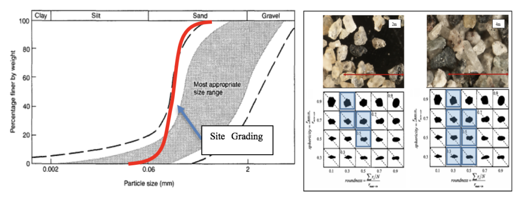
The M2PP deposits have typically 1% passing the 0.063mm sieve and 80% passing the 0.15mm sieve with a uniformity coefficient of 1.49. The sand also had a high sphericity typically of 0.5-0.9 and regularity of 0.5-0.6. These factors affect the packing and thus the achievable density and strength (mechanical interlock) and porosity. In Figure 5 the Holocene dune sand grading curve is compared to the range of particle sizes for which vibro-compaction should be effective (CIRIA Report C572 2002). The Authors have concluded that the particle shape and uniformity are also important factors to consider in assessing the potential for sand to respond to vibro-methods.
Figure 5: Holocene dune sand macro photography, grain shape assessment and grading curve compared to the range of particle sizes for which vibro compaction should be effective (modified from CIRIA Report C572 2002).
6.2 Vibro-Replacement (Stone Column)
The observations from the vibro-densification trials were partially reflected in the Vibro-replacement trails. Area replacement ratios of 21%, 25%, 33% and 35% were trialled with CPT soundings taken immediately prior to treatment and seven days following treatment. Densification was not as effective as expected and a very high replacement ratio was required to achieve satisfactory densification in the medium dense sands. Replacement ratios of 21% and 25% showed little to no densification improvement and a replacement ratio of 33% showed reasonable improvement. An increase to a 35% replacement ratio did not yield any further improvement.
Another notable, but not entirely unexpected response, was that sands in the vicinity of silt interbeds did not appear to improve. These zones, typically not more than 500mm thick, associated with thin (<100mm) and laterally discontinuous silt layers could not be improved to meet the minimum qt values. These were considered unlikely to compromise the overall performance of the ground improvement in a ULS event.
The authors concluded that published guidance on target replacement ratios, such as the work from Baez (1995) and Priebe (1995), does not provide a reliable indication of effective replacement ratios in these soils, and that this was due to their uniform grading and sphericity.
6.3 In-situ Mixing
Laboratory soil/cement mixing trials were completed on two sand samples taken at 2m and 4m depth. The geologic origins of these sands is thought to be similar (dune deposits) however their characteristics differ somewhat and this is reflected in their response to the use of a cement binder. Table 1 summaries the difference in soil characteristics between the two samples.
Table 1: Comparison of sand properties from Otaihanga Road Overpass
| Origin | Otaihanga 2m depth | Otaihanga 4m depth |
| Description | Fine quartzose dune sand | Fine quartzose dune sand |
| Grading | Generally within the 0.1 to 0.2mm size range, 15% fines. | Generally within the 0.1 to 0.2mm size range, 2% fines |
| Cu | 1.8 (may not fully reflect the uniformity in the sand due to presence of fines) | 1.5 |
| Sphericity | 0.5-0.9 | 0.3-0.9 |
| Regularity | 0.5-0.6 | 0.3-0.6 |
| Dry Density | 1.33 t/m3 (compacted) | 1.51 t/m3 (compacted) |
| Porosity | 50% | 44% |
| UCS at 6% | 45 kPa | 150 kPa |
| UCS at 9% | 50 kPa | 380 kPa |
| UCS at 12% | 50 kPa | 800 kPa |
| UCS at 20% | 50 kPa | 1500 kPa |
The generally poor test results meant that the in-situ mixing method was non-viable with cement contents of more than 20% and high variability in results. These results were considered to be affected by the high uniformity of the sand which in turn, resulted in a high void ratio which appears to have prevented efficient cementation. Work completed by Consoli et al. (2012) demonstrating the variation of unconfined compressive strength (qu) with porosity of cemented soils appears to be consistent with the range of UCS results achieved with both the 2m and 4m samples (refer figure 6).
|
|
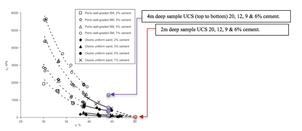
Figure 6: Variation of UCS (qu) for cemented soils with porosity (modified from Consoli et al. 2012) compared with the UCS results from Otaihanga sand samples.
The authors concluded that while the grading and composition of the sands are similar, the effect of porosity can have a significant impact on engineering behaviour of artificially cemented soils.
7 CONCLUSIONS
A number of different ground improvement methods were trialled in saturated dune sands and found to be unsuccessful or requiring the utilisation of very high area ratios to achieve the desired level of improvement.
The sands to be improved were notable in that the grains were fine, uniform and comparatively spherical. As a consequence these sands were found to be more difficult to compact or to cement than would have been expected if assessing simply based on fines content or CPT soil behaviour Index. Vibro-compaction was found to be unsuccessful, vibro-repacement provided limited success, requiring very high area ratio and cement stabilisation was not consistent even at very high binder contents
These findings lead to a number of lessons learnt for the project team, the most significant being that widely adopted, empirically based correlations for ‘improveability’ of sands based on fines content/plasticity and soil behaviour indices, may be unreliable when applied to soils with high uniformity, sphericity and porosity.
8 ACKNOWLEDGEMENTS
The authors would like to thank the MacKays to Peka Peka Expressway Alliance, Nick Wharmby (formally Brian Perry Civil) and David Chadwick (Keller GE Australia). The authors would also like to thank the New Zealand Transport Agency who granted permission to publish this paper.
REFERENCES
Barksdale, R.D. and Bachus, R.C., (1983) Design and Construction of Stone Columns, Volume I. Report No FHWA/RD-83/026, Federal Highway Administration, Washington, D.C.
Baez, J. I. & Martin, G. R. (1993) Advances in the Design of Vibro Systems for the Improvement of Liquefaction Resistance. Proceedings of the 7th Annual Symposium of Ground Improvement.
CIRIA Report C572. (2002) Treated ground: engineering properties and performance. CIRIA London.
Coe, L. J., and Alexander, G. J., (2012) MacKays to Peka Peka Expressway: Road Embankment Construction on Peat Deposits. Proceedings of the 11th Australia and New Zealand Conference on Geomechanics (ANZ 2012).
Consoli, N.C., Rosa, D.A., Cruz, R.C. and Rosa, A.D. (2011) Water content, porosity and cement content as parameters controlling strength of artificially cemented silty soil. Eng. Geol., 122(3-4), 328-333.
Consoli, N.C., Fonseca, A.V., Silva, S. R., Cruz, R.C. and Fontini, A. (2012) Parameters controlling stiffness and strength of artificially cemented soils. Geotechnique, No. 2, 177-183.
Mitchell, J. (1981) Soil Improvement – State of the art report. Session 12. Amelioration des Sols.
Ngyugen, T.V., Rayamajhi, D., Ashford, S.A., Boulanger, R.W., Lu, J., Elgamal, A. & Shao, L. (2012) Effect of DSM grids on shear stress distribution in liquefiable soil. ASCE Geo Congress Conference, Oakland, California, March 25-29.
OTREC (Oregon Transportation Research and Education Consortium) (2013) Reducing Seismic Risk to Highway Mobility: Assessment and Design Examples for Pile Foundations Affected by Lateral Spreading. Oregon Dept. of Transportation.
Priebe, H.J. (1995) The Design of Vibro Replacement. Ground Engineering, Technical Paper GT 07-13 E, 1995.