Geotechnical Design for Severe Liquefiable Ground Improvement with Subsurface Compacted Rubble Raft (SCRR) Technology
A Waikato Region Case Study
Abstract
This paper presents an innovative geotechnical design approach using patented Subsurface Compacted Rubble Raft (SCRR) technology to improve severe liquefiable ground. It’s exemplified through a case study in New Zealand’s Waikato Region, particularly the Ngahinapouri Village new development site in Waipa, Waikato. This study originates from collaborative research by Wintec and GECNZ, aiming to introduce SCRR technology to the region. This is part of a series of three sample sites for demonstration purposes, which include the Endeavor Ave site, Ngahinapouri Village new development site, and Te Awamutu site. The primary objective is to guide SCRR construction, mitigating liquefaction hazards at Ngahinapouri Village New Development site. The goal is to upgrade its Technical Category (TC) classification from TC3 to TC1, aligning with residential lot criteria by the Ministry of Business, Innovation, and Employment (MBIE). The study underscores the region’s urgent need for disaster preparedness, with over 20% of Waikato land susceptible to medium/high liquefaction damage, and 90% of Hamilton land facing medium to high liquefaction vulnerability. SCRR technology, with its versatile mechanisms of replacement, densification, reinforcement, solidification, and drainage, is a promising solution for extreme liquefaction risks, avoiding excessive ground treatment. This design offers a comprehensive overview of critical SCRR construction parameters, such as thickness, depth, layer count, bulb specifications, and material requirements. Furthermore, it introduces four design methods to determine SCRR raft dimensions. As an emerging technology, this paper provides a concise guide to SCRR construction procedures, emphasizing quality control measures, including Cone Penetration Testing (CPT), and strict adherence to MBIE requirements. These insights aim to enhance understanding among geotechnical engineering practitioners.
1. Introduction
The Waikato region’s susceptibility to liquefaction is primarily due to its geological makeup, including the Waikato Basin’s sedimentary deposits. Over 20% of the region is classified as having a high to medium liquefaction vulnerability, according to the Liquefaction Level A distribution map (Waikato Regional Council, 2023). In Hamilton City, over 90% of the area is susceptible to liquefaction damage, making it crucial to find solutions to address this issue (Tonkin & Taylor, 2019).
The Waipa district, particularly Ngahinapouri, is projected to experience substantial growth by 2050 (Tonkin + Taylor, 2019). To accommodate this, structure plans are required for growth cells in Ngahinapouri (Figure 1), as outlined in the Waipa 2050 Growth Strategy and the Waipa District Council’s Long-Term Plan. The site in question encompasses three growth cells (Cells N1, N2, and N3) across approximately 102 hectares on both sides of Reid Road. According to Tonkin and Taylor (2019), Cell N2 was historically subject to mining, while the remaining cells are of alluvial origin. Ngahinapouri is located in a flat region within the Hamilton Basin, with minimal natural landscape changes except for the Mangahia stream along its northern boundary. There is a former sand mining area in the northwest corner of the site, with uncertain records of its filling, marked on the Geomorphic Plan. The majority of the site is classified as Alluvial Plains. Tonkin & Taylor Ltd conducted the geotechnical desktop study, which showed a high risk of liquefaction in the growth cells (Tonkin + Taylor, 2019), necessitating the use of innovative ground improvement techniques, such as the Subsurface Compacted Rubble Raft (SCRR) technology.

Figure 1: Ngahinapouri Village New Development Cells N1, N2, and N3, adapted from Tonkin and Taylor (2019) and Google Map.
Managing liquefaction-related risk involves several options, including avoiding construction in vulnerable areas, using specific foundations, and performing ground improvement. This paper focuses on ground improvement, particularly the use of SCRR technology, as an effective solution to enhance resilience and protect infrastructure and dwellings from potential disasters in the region.
GECNZ has introduced an innovative ground improvement technique known as Subsurface Compacted Rubble Raft (SCRR or SCR Raft) (Du and Shahin, 2016; Du and Xu, 2023). SCRRs are a patented ground improvement solution designed to effectively address severe liquefaction issues. SCRRs target liquefaction-prone layers by creating a horizontal artificial layer within the shallow subsurface using compacted rubble spheres. The primary goal is to upgrade land with liquefaction risks to meet TC1/TC2 criteria, enabling standard foundation construction for buildings. GECNZ is preparing a pilot project in Canterbury for late 2023 to transition SCRR from research and development into a practical product. The goal of the pilot project is to evaluate SCRR functionality, refine its design specifications, and prepare for full-scale production, set to commence later in 2023 (Du and Xu, 2023).
Our initial research has shown that the percentage of land with high liquefaction vulnerability in each major city in New Zealand is estimated as not less than 10% (corresponding to a total value of $30 billion) (EQC and Tonkin & Taylor, 2015; Greater Wellington Regional Council, 2021)(Greater Wellington Regional Council, 2021). SCRR technology aims to upgrade such land, with tens of thousands of land sections facing this issue. The high liquefaction vulnerability in major cities, such as Wellington and Hamilton, underscores the need for effective solutions. The SCRR technology is anticipated to have extensive market coverage, addressing liquefaction issues in residential, commercial, and industrial areas. The release of the National Seismic Hazard Model in 2022, indicating increased earthquake shaking hazards, further emphasizes the need for resilient strategies and readiness (Steeman, 2019; Houtte et al., 2022).
SCRRs offer several advantages, including cost-effective wide-area improvement, full land repair, and efficiency in land preparation for construction projects. Overall, SCRR technology represents a promising solution to address liquefaction hazards and enhance land resilience in New Zealand.
2. Geotechnical Investigation and Liquefaction Analysis
2.1 Geotechnical investigation
NZGD initially supplied geotechnical investigation data via its online platform, including Cone Penetration Tests (CPTs), Hand Auger samplings, and Dynamic Cone Penetrometer (DCP) tests. These tests were conducted within Cell N1 of the site by Drillforce and HD Geo both in 2018. However, it is noteworthy that no investigations have been documented for Cells N2 and N3 (Figure 1).
Sub-surface testing completed for this site comprised:
- 10 Cone penetration tests (CPT) to 20m or refusal
- 16 Hand Auger (HA) tests with engineering geological logging of recovered material, and
- 16 Dynamic Cone Penetration (DCP) tests to assess bearing capacity for foundation design.
This section mainly focuses on introducing the deep ground investigation, preparing for the liquefaction analysis and ground improvement design in the following sections. Shallow investigations are not discussed in detail in this article.
The liquefaction desktop study recommended a Level C assessment based on Cone Penetrometer Testing, borehole log information, and groundwater monitoring. The CPT data showed that the site primarily consists of sand and silty sand layers extending to a depth of 20 meters. These layers were occasionally mixed with clay and silt layers. The cone resistance values ranged from 5 to 10 MPa in sandy segments, while clay and silt layers had lower resistance readings.
Geotechnical data from the current site, along with observations from HA, DCP, and CPT boreholes, indicated the presence of groundwater at different depths, ranging from 2.4 to 3.5 meters across the site as reported by Tonkin and Taylor (2019). According to NZGD data from 2023, the groundwater depth reaches a maximum of 4.7 meters (NZGD, 2023). The Tonkin and Tayler report concludes that additional CPTs will be required for future subdivision and detailed design work, and the data collected is sufficient for the preliminary design phase (Tonkin + Taylor, 2019).
Ground liquefaction vulnerability classification is the prerequisite for ground improvement design. Different approaches, including Liquefaction Vulnerability Category (MBIE, 2017), Liquefaction Severity Number (LSN) (Ballegooy et al., 2014), Liquefaction Potential Index (PLI) (MAURER et al., 2015), Technical Category (TC) (MBIE, 2012), and the Lateral Displacement Index (Zhang, Robertson and Brachman, 2004), have been developed to assess and communicate potential land performance concerning liquefaction hazards. Technical Categories (TC) will be primarily used in this design, but other tools, such as Liquefaction Severity Number (LSN) and Liquefaction Potential Index (LPI), can serve as valuable indicators for specific areas or sites.
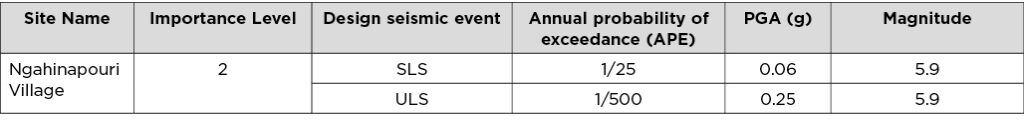
The chosen subsoil class for the project is Class D (Deep Soil Site), determined through a site-specific seismic hazard assessment. Seismic design parameters, including peak ground accelerations (PGAs) and magnitudes, have been established according to guidelines from MBIE Module 1, with a summary of these parameters presented in Table 1.
Table 1: Design peak ground accelerations and corresponding magnitudes for geotechnical assessment (MBIE, 2021).
2.2 Liquefaction analysis methodology
During an earthquake, the cyclic ground motion can lead to changes in soil characteristics, including increased pore-water pressure, decreased soil strength, and diminished bearing capacity of the ground. If the excess pore pressure becomes sufficiently high, liquefaction can occur, leading to surface manifestations like soil and water expulsion or dissipation into the surrounding soil. After liquefaction, soil particles settle back, causing ground surface settlement (AECOM, 2019).
A study of the seismic behaviour of the soil was conducted using CLiq v.3.5.2.19, a software developed by GeoLogismiki (Geologismiki, 2018). The analysis employs results from CPT tests and adheres to the methodologies recommended by MBIE Module 3, page 26 (MBIE, 2021) as:
- Analysis method: Boulanger and Idriss (2014)
- Fine correction following Boulanger and Idriss (2014)
- Vertical Settlements in line with Zhang et al. (2002)
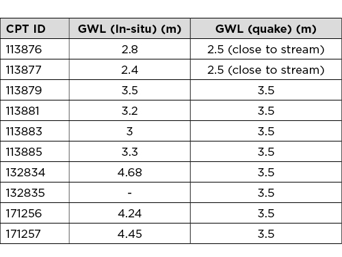
To gauge the susceptibility of the soil’s seismic response, an evaluation was performed based on in-situ CPT testing conducted at the Site. For this assessment, an earthquake groundwater level of 2.5m for 2 CPTs close to the stream (113876 and 113877), and 3m for other 8 CPTs Below Ground Level (BGL). This value is derived from groundwater encountered in hand-augured drillholes, dip levels noted within CPT holes, or estimated through dynamic pore pressure plots when dipping wasn’t possible due to hole collapse (Tabel 4) (NZGD, 2023).
Table 2: the in-situ depth to groundwater table for each CPT.
2.3 Vertical Settlement and Lateral Spreading
Referencing the MBIE guidelines from December 2012, a comprehensive liquefaction analysis of the entire soil profile at SLB1, SLB2, and ULS shaking, is typically necessary for foundation design. However, for the SCRR technique, an analysis of the soil profile under Ultimate Limit State (ULS) level shaking is required. A summary of the results is provided in Table 3 below.
Table 3: Summary of performance levels: liquefaction analysis of full CPT trace at ULS ground shaking.

Table 3 highlights that among the ten CPTs, vertical settlements exceed 100mm for all except CPTs 113876 and 132835, which have values of 77 mm and 92 mm respectively (in bold). These two CPTs possess high LSN values of 16 and 21. Remarkably, all the CPTs exhibit high LSN readings surpassing 15, along with eight high CPT settlement interpretations larger than 100mm, indicating TC3 criteria soil. It is worth noting that these 10 CPTs are located in N1 Cell. The report by T & T (2019) explicitly identified Cell N2 as having non-engineered fill and a high liquefaction vulnerability. No data for N3 Cells have been found to categorize this lot. Considering MBIE’s assessment guidance from 2012 and the discussion in previous section, in conjunction with Table 3, the site is initially categorized as a Technical Category 3 (TC3) site. Moderate to severe land damage may be expected to occur in a ULS-level event.
Based on the results of the liquefaction assessment, it appears likely that liquefaction mitigation is required to raise the site’s classification from TC3 to either TC1 or, at the very least, TC2, in accordance with MBIE’s guidelines. The planned SCRR ground improvement solution in this design is intended to elevate the site’s classification to meet TC1 criteria.
Given the site’s predominantly flat topography and most of the site has considerable distance from the small stream or exposed slopes in the immediate vicinity, it is reasonable to anticipate that there will likely be limited lateral movement during a seismic event, except for the adjacent area near the shallow river. The site is categorized as TC3, and the SCRR design solution for TC3 land remediation is specifically engineered to withstand potential lateral spreading due to its pyramid structure and strong interlocking mechanism (Du and Xu, 2023).
3. Ground Improvement Techniques and Design Consideration
The ground improvement process involves five primary mechanisms: replacement, densification, reinforcement, solidification, and drainage, as detailed in MBIE Module 5 (MBIE, 2021). For example, stone columns can encompass several of these mechanisms (Tang and Orense, 2014). SCRR, however, encompasses all five mechanisms, making it versatile and applicable across various soil types (Du and Xu, 2023).
Unlike other methods like stone columns, which may have limited strain transfer and reinforcing effects due to its lower compaction power applied and poor compact effect of even grading particles; however, SCRR generates high strain in the surrounding soil during installation attributing to its high compaction power and strong interlocking effects of mix-sized rubble materials. This leads to interlocked particles and stiff SCR raft formation, significantly enhancing ground resistance to settlement and lateral movement (Nguyen et al., 2013; Rayamajhi et al., 2014; Oregon State Government USA, 2023). SCRR, therefore, offers a solution for severe liquefaction problems, such as the 8,000 red zoned land left untreated for over 12 years (Du and Xu, 2023).
Furthermore, SCRR treatment introduces a secondary improvement mechanism as it displaces soil during casing installation and rubble bulb construction. This process increases lateral stress, further enhancing soil resistance to liquefaction, aligning with the requirements recommended by MBIE Module 5 (MBIE, 2021).
According to Elias et al. (2017), the vibratory replacement method that SCRR treatment uses suits most soil types ranging from clay to large gravel. SCRR’s compatibility with various soil types, from clay to large gravel, makes it a versatile solution for varying geotechnical conditions and effective for land prone to high liquefaction vulnerability.
The Ministry of Business, Innovation and Employment (MBIE) collaborated with the New Zealand Geotechnical Society (NZGS) to develop comprehensive earthquake geotechnical engineering guidelines, encompassing six modules published in December 2021. Our SCRR design and assessment adhere to these guidelines, including Modules 1 to 6, as well as MBIE’s 2012 Modules A to E. In the context of SCRR ground improvement, we recommend reviewing the following resources:
- MBIE. (2012).. “Repairing and Rebuilding Houses Affected by the Canterbury Earthquakes, Parts A, B, C, D, E.” The Ministry of Business, Innovation and Employment, New Zealand.
- MBIE. (2021). “Earthquake Geotechnical Engineering Practice, Modules 1 to 6.” The Ministry of Business, Innovation and Employment.
- Earthquake Commission New Zealand. (2011). “Appendix A: Assessment of Liquefaction Vulnerability in Christchurch.” (Earthquake Commission New Zealand, 2015).
Our SCRR design and construction adhere to key principles, which are in alignment with the mentioned standards and guidance:
- Targeting Problems Directly and Avoiding Excessive Treatment: SCRR focuses on addressing the uppermost liquefiable layer(s) to manage settlement and lateral spreading while avoiding unnecessary treatment. It is suitable for remediating TC3/red zoned land to TC1/TC2 criteria (Du and Xu, 2023).
- Direct Thickening of CRUST/RAFT: SCRR generally thickens the total crust by more than 3 meters to enhance performance levels. Partial depth treatment is recommended to mitigate settlement and lateral spreading (Wansbone and van Ballegooy, 2015) , also recommended by Earthquake Commission New Zealand (2011) and MBIE (2021).
- Strong Pyramid Structure: SCRR construction utilizes a reliable and simple structure where each bulb in the upper layer is positioned at the center of the three lower bulbs in the bottom layer, forming a stable pyramid structure (Du and Xu, 2023).
- Strong Interlocking of Mixed-Sized Particles: The use of mix-sized, non-purposely processed aggregates in SCRR ensures optimal compaction and high interlocking forces between aggregate particles, promoting the formation of a dense SCRR conglomerate cost-effectively.
- SCRR Incorporates Five Mechanisms: replacement, densification, reinforcement, solidification, and drainage mechanisms, making it suitable for diverse soil types.
Limitations:
- Large Machinery: Requires relatively large machinery.
- Relocation of Existing Houses: May necessitate temporarily moving houses for treatment.
- Obstructions: Underground utilities or obstacles can hinder installation.
- Limited Effectiveness in Cohesive Soils: May be less effective in cohesive soils.
4 Design Parameters and Analysis
This section discusses the major parameters of the SCR rafts and determines the SCRR thickness, depths, and the bulb dimensions, explore the site mark out, and present the requirements for the SCRR materials.
4.1 Natural crust and natural rafts
It has been observed that buildings situated on denser, stiffer, and thicker non-liquefiable crusts suffered considerably less damage during the Canterbury earthquake sequence when compared to structures resting on looser, less stiff, and thinner near-surface natural rafts. These denser, stiffer, and thicker non-liquefiable natural rafts exhibit superior CPT and cross-hole geophysical soil parameters, including shear-wave velocity. Shallow-subsurface ground improvement methods aim to augment the thickness and/or stiffness of near-surface soils, thereby enhancing liquefaction resistance (Earthquake Commission New Zealand, 2015; MBIE, 2021). This SCRR approach essentially seeks to replicate the performance of well-performing natural soil rafts during earthquakes.
MBIE has proposed that where a “natural raft” is unavailable or inadequate for liquefaction resistance, an “artificial raft” can serve as a suitable alternative. This artificial raft can be created through the implementation of a specialized ground improvement technique (MBIE, 2021). The SCRR treatment addresses this requirement by thickening the near-surface crust, starting from the base of the natural crust. This involves displacing the uppermost liquefiable layer directly beneath the natural raft while simultaneously compacting the underlying liquefiable layer. A stiff SCRR crust demonstrates greater resilience compared to a less stiff natural raft or crust, or other artificially constructed crusts with weak particle interlocking mechanisms and lower compact power. Consequently, the SCRR approach offers improved mitigation against potential differential settlement and lateral spreading with its horizontal treatment solutions. Therefore, SCRRs may be one of the most typical “Artificial Raft” methods.
4.2 Layout and spacing of SCRR bulbs and raft
The configuration and arrangement of SCRR elements involve arranging bulbs in a triangular pattern, typically with a spacing between bulbs of 1.5 to 2.0 m and a bulb diameter ranging from 1.0 to 1.5 m. This arrangement follows a two-layer installation structure, as illustrated in Figure 2.
Each bulb in Figure 2 is encompassed by a surrounding zone of densified soil. According to the cavity expansion theory (Yu, 2000) and numerical modelling (Du and Xu, 2022), the annular layer of the densified soil possesses a thickness not less than the radius of the bulb.
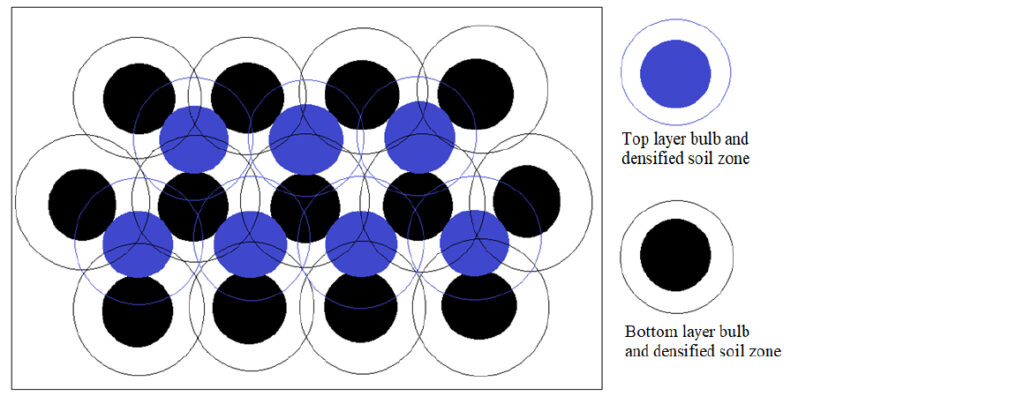
Figure 2: the triangular arrangement of SCRR bulbs within a two-layer installation structure.
4.3 SCR Raft Dimensions and Bulb Design
SCRRs should possess adequate thickness to effectively restrain and bridge over any below liquefiable or weak soils. In instances where the liquefiable soil layer is relatively thin, full-depth treatment is a viable option. However, for most sites, the thickness of liquefiable layers typically ranges from 5 to 10 m. Due to cost and technical considerations, achieving full-depth improvement throughout an entire land section becomes impractical (MBIE, 2021).
Data gathered from over 60,000 investigations into the performance of family bungalows during the Canterbury earthquake sequence has revealed that structures supported by a natural stiff raft/crust, with a thickness of at least 3 m, suffered less damage (Wansbone and van Ballegooy, 2015). Consequently, partial depth treatment can yield satisfactory performance by effectively mitigating settlement and lateral spreading, as recommended by relevant guidelines and practices (Earthquake Commission New Zealand, 2015; MBIE, 2021). Therefore, SCRR solutions aims at adding a SCR raft immediately below the top natural crust to increase the crust total thickness larger than 3 m. There are multiple methods employed to estimate SCRR thickness and installation depth, which are explained as follows:
Method One – Using Cliq CPT Settlement Graph to Estimate SCRR Treatment Soil Range
The Cliq settlement graph (Figure 3) below illustrates the results of 10 CPT analyses, depicting variations in vertical settlement. These variations are mainly observed within the range of 3.0 to 18.5 m on the right graph. That means the SCR raft needs to mitigate the liquefaction hazards occurrence from 3.0 to 18.5m. This doesn’t mean the SCR raft needs to replace all the liquefiable soil from 3.0 to 15.5m. To avoid excessive/unnecessary treatment, partial treatment is more practical (MBIE, 2021). The more accurate thickness of SCRR treatment will be introduced in the following methods.
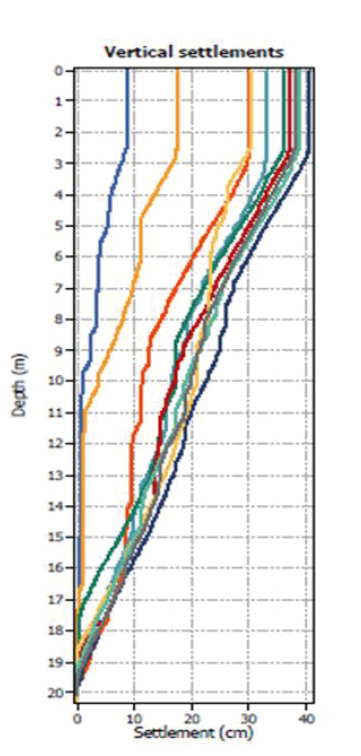
Figure 3: Using settlement graph of 10 CPTs to estimate SCRR treatment soil range.
Method Two – CLiq Back Calculation Method for Approximating Treatment Ranges
Cone penetration testing (CPT) is commonly employed for design and quality control (QC) purposes after ground improvement (Geologismiki, 2018). Within CLiq, this can be accomplished through the back calculation of the cone resistance profile, qc. tested from the site before treatment. Typical CPT113883 represented a worst scenario of settlement. The results of the back calculation for a single CPT profile under TC3 criteria by MBIE are presented in Figure 4. The design cone profile is highlighted in red, overlaying the measured cone profile in black.
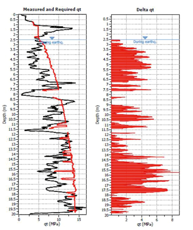
Figure 4: Back calculation of CPT113883 showing liquefiable layers in red (right) requiring improvement.
As depicted in Figure 4, the segments necessitating ground improvement are situated within the 3.0 ~ 19 m range for CPT113883, comprising liquefiable soil ranges in red, and separated with non-liquefiable soil in blank in the right graph. The graph is used to estimate the accumulative thickness of the liquefiable soils, which is around 9.0 m from 2.5 to 20 m depth. This accumulated thickness will be used for calculation in Method Four.
It is evident that some non-liquefiable soil layers, especially from 7.0 to 14 m, are interbedded with the liquefiable soil layers. According to MBIE Module 3, small detected or undetected lenses of liquefiable soils are unlikely to cause major damage but the risk of damage increases with increasing spatial extent of such deposits (MBIE, 2021). SCRR treatment is a full land solution, so the spatial extent effect is limited.
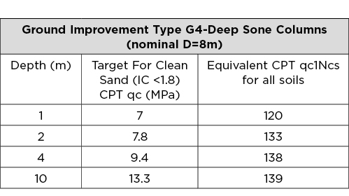
Method Three – Using Target Soil-densification Criteria Approach
MBIE (2021) has provided guidance for testing ground improvement criteria for stone column technique as presented in Table 4. It can be used for initial design of SCR raft to improve the sandy soils to a resistance above a certain value. It is noted that the preliminary target CPT cone penetration values (qc) in Table 4 are only defined for sand, that means the sand soil should meet these requirements. It is not applicable to non-liquefiable soils, i.e., clay soil encountered in the ground. The CPT qc1Ncs values in the right column are defined for all kinds of soils. The normalized clean sand equivalent CPT tip resistance, qc1Ncs, is a function of the CPT tip resistance (qc), the groundwater depth (GWD), the fine content (FC) determined through laboratory testing, and soil density. It is a complex parameter and is not recommended for use in the initial design of an SCRR solution (Earthquake Commission New Zealand, 2015).
Table 4: Target soil-densification criteria up to 10 m adapted from MBIE Guidance Part C (MBIE, 2012).
According to Table 4, if a line is drawn in Figure 5, with the coordinates from the Columns 1 and 2. Then the red straight line indicates the CPT resistance to meet if the soil is sand.
Figure 5 shows that ground improvement should target the depth between 2-4 m and 10-16 m. The findings of this analysis align with those obtained through the preceding two methods as the Methods 1, 2, and 3 point to the very similar depth ranges of 2-4 m, 8-9 m, and 10-16 m. The lower dot line represents the proposed CPT resistance of soil below 10 m, where the liquefaction risks are minor for shallow foundation structure after treatment above 10 m, because, mostly, the liquefaction potential below 10 m after SCR raft installation will be bridged over as discussed in the previous sections.
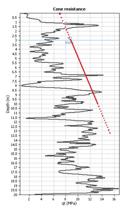
Figure 5: typical CPT113883 profile with the target resistance line.
Based on the above analysis, a preliminary conclusion can be drawn that the treatment depth provided by the SCR raft can be tentatively determined to range from approximately 3.0 m to around 10 m. A more precise treatment depth and thickness will be elaborated upon in the subsequent methodological discussion in Method Four.
Method Four – Estimation Using Ishihara Crust Theory and Graph
Ishihara (1985) observed that for a site characterized by a crust with a thickness larger than the underlying liquefiable layer (Figure 6), the ground damage due to liquefaction will be mitigated or avoided. This theory supports well with SCRR treatment mechanism that the SCRR raft can well increase the thickness of the total CRUST after SCRR installation. The buried depth of an SCRR is generally greater than 3 m to control ground heave.
There are three shaking scenarios provided by Ishihara (1985). When subjected to seismic shaking loading at an intermediate value such as 0.25g in Waikato, a novel curve line can be drawn between the lines of 0.2g and 0.3, as shown the red line in Figure 6. For the Site, where the natural crust is estimated to be 3 m thick (H1) at CPT113883, the SCRR is installed from a depth of 3 m downwards. then the thickness of the SCR raft Hs can be calculated, by the following steps:
- First, the liquefiable layers of CPT113883 in Figure 4 have a cumulative thickness of 9 m (H2).
- Second, locate H2 = 9 m in the curve line that is matching the right shaking value 0.25g (Figure 6), the new total crust thickness H’1 required can be read out as 4.8 m.
- Then, the SCRR thickness can be computed:
Hs ≥ (H’1-H1 ) = 4.8 – 3.0 = 1.8 m, so Hs > 1.8m
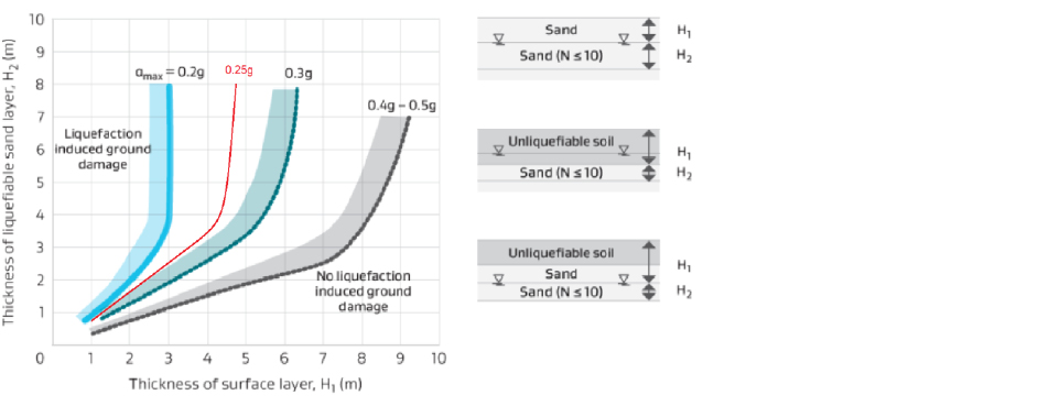
Figure 6: Chart for evaluation of the effect of crust thickness on liquefaction triggering adapted from Module 3 of MBIE (2021).
Therefore, the rubble diameter is designed to be 1.2 meters, with a densified soil thickness of 0.6 meters both above and below the rubble bulbs. This results in a total SCR raft thickness of 2.4 meters. Consequently, the one-layer SCR raft will be installed starting at a depth of 3 meters. The lower interface of the SCRR rubble bulb is positioned at a depth of 5.4 meters below ground level (BGL), and the ground is expected to be upgraded to TC2/TC1 level.
It’s important to acknowledge that the four methods mentioned above have been developed with distinct objectives, each carrying its own set of advantages and disadvantages. The SCRR design method brings together these four approaches to enhance practitioners’ comprehension of SCRR design. Readers are encouraged to contribute and propose improved design methods.
4.4 SCRR Compaction and Material
The level of “saturation energy intensity” in ground improvement determines the material density and resistance to liquefaction. Module 5 in MBIE (2021) provides a method for predicting energy used in dynamic compaction. For the SCRR ground improvement, a cut-off SPT value of 20 blows is recommended for a seismic event with a PGA of 0.4 g. This corresponds to an applied energy of approximately 1.5 MJ/m2 for sand and gravel. If a closed-end casing with a 400 mm diameter is used for rubble compaction under vibratory hammer compaction, the required power for SCRR compaction should be at around 190 kN m.
Selecting suitable ground improvement materials to secure a site during earthquakes involves considering factors such as cost, stability, and environmental friendliness. Most ground improvement practices use inert materials that undergo minimal chemical, physical, or biological reactions to minimize ground contamination (MBIE, 2021). SCRR rubble, including waste materials like brick, concrete, hardcore, quarry tailings, and river run, meets these requirements (Du and Shahin, 2016; Du and Xu, 2023). Uniformly graded gravels are less effective for forming dense conglomerates, and their processing is costly and energy-intensive (Penn State University, 2021). In contrast, mix-sized, non-processed aggregates with high friction and dilation angles are more cost-effective and facilitate optimal compaction in SCRR installations. The rubble particle size ranges from 10 to 200mm.
5. Construction Methodology and Quality Assurance
An SCRR project involves ten processes to complete the construction of an SCRR raft. These processes include the installation of the 1st bulb, 2nd bulb, 1st line of bulbs, 2nd line of bulbs, 1st layer of SCRR, and 2nd layer of SCRR for a two-layer SCRR structure. A summarized representation of the SCRR construction process is provided in Table 5 below.
Quality control (QA) measures for Subsurface Compacted Rubble Raft (SCRR) construction involve various testing methods, including Cone Penetration Testing (CPT) for rubble materials, CPT testing of liquefiable soils between SCRR bulbs, Standard Penetration Test (SPT), and SCRR profile verification using coring and shear-wave testing. MBIE guidelines provide criteria for testing ground improvement (MBIE, 2021), which are applicable to SCRR construction verification. The target resistances for the sand soils are:
- CPT (uncorrected), qc value target refers to Table 4.
- SPT (uncorrected) > 20; or
- Dynamic cone penetrometer (Scala) > 10 blows per 100 mm.
Dynamic compaction typically demonstrates late strength gains, with final QA testing scheduled with a 2-week delay after ground treatment completion (MBIE, 2021). The target for clean sand in a stone column installation is initially used for SCRR target validation. The target resistance values for sand soils at different depths are specified in Table 4. In cases where the minimum degree of improvement defined by the criteria is not achieved, the contractor is required to inform the engineer for further analysis, correction, and possible rework as per MBIE guidelines.
Table 5: SCR Raft construction process including 10 sub-steps for creating a SCRR bulb.

6. Conclusion
This paper highlights the following key points:
- A significant portion 20% of the Waikato region, including 90% of Hamilton City, is susceptible to high/medium liquefaction vulnerability, emphasizing the need for disaster preparedness solutions.
- The Technical Category (TC) method is used for Subsurface Compacted Rubble Raft (SCRR) design and construction validation, with the Site classified at TC3 level.
- The paper presents a design of SCRR solution for the Ngahinapouri Village site in Waipa, with the aim of elevating the site’s classification from TC3 to TC1.
- Several key principles are applicable to SCRR design and construction, including addressing the problem layer directly, using effective material mix, stable pyramid construction, thickening and strengthening the natural crust, and employing versatile techniques.
- The design brief for SCRR construction at Ngahinapouri Village specifies a one-layer SCRR structure with specific dimensions, rubble bulb thickness, construction machinery, and quality control measures.
This design serves as an example for demonstration purposes. It will need field testing to validate its effectiveness in upcoming projects, such as the scheduled pilot project. The paper acknowledges limitations, including data sourced from various investigations and studies, with no guarantee of accuracy or completeness. Additionally, variations in soil characteristics and site testing may exist.
Acknowledgement
The authors would like to acknowledge the contribution of the Callaghan Innovation and Trust Waikato in supporting this research.
References
AECOM (2019) Endeavour Ave Development, Hamilton Geotechnical Assessment Report. Hamilton.
Ballegooy, S. van et al. (2014) ‘Assessment of Liquefaction-Induced Land Damage for Residential Christchurch’, Earthquake Spectra, 30(1), pp. 31-55.
Du, Z. and Shahin, M. A. (2016) ‘Subsurface Compacted Rubble Raft Technology for Ground Improvement’, in ISC’5 (ed.) The 5th International Conference on Geotechnical and Geophysical Site Characterisation (ISC’5). Australian Geomechanics Society, Sydney, Australia, pp. 1331–1336. Available at: http://australiangeomechanics.org/public-resources/downloads/#dlISC5 Proceedings.
Du, Z. and Xu, S. (2022) ‘Bearing Capacity Design of Ram-Compacted Bearing Base Piling Foundations by Simple Numerical Cavity Expansion Approach’, International Journal of Geomechanics, 22(2), p. 13.
Du, Z. and Xu, S. (2023) ‘Field miniature prototype development and pilot project design of subsurface compacted rubble rafts (SCRRs )’, in Proceedings of NZSEE2023, p. 20.
Earthquake Commission New Zealand (2015) Canterbury Earthquake Sequence: Increased Liquefaction Vulnerability Assessment Methodology – Appendix A : Assessment of Liquefaction Vulnerability in Christchurch, Canterbury Earthquake Sequence: Increased Liquefaction Vulnerability Assessment Methodology. New Zealand. Available at: https://www.eqc.govt.nz/assets/Canterbury-earthquake-page-documents/ILV/Appendix-A.pdf (Accessed: 26 December 2022).
EQC and Tonkin & Taylor (2015) Canterbury Earthquake Sequence: Increased Liquefaction Vulnerability Assessment Methodology, Appendix M : Classification Process for Properties that do not Qualify for ILV but are Materially Vulnerable to Liquefaction. Available at: https://www.eqc.govt.nz/assets/Canterbury-earthquake-page-documents/ILV/Appendix-M.pdf.
Geologismiki (2018) CLiq User’s Manual, CLiq – Liquefaction assessment software from CPTU measurments -User’s Manual.
Greater Wellington Regional Council (2021) Wellington_Region_Liquefaction_Potential, https://data-gwrc.opendata.arcgis.com/. Available at: https://data-gwrc.opendata.arcgis.com/.
Houtte, M. C. G. C. Van et al. (2022) New Zealand National Seismic Hazard Model Framework Plan. Edited by The Institute of Geological and Nuclear Sciences Limited (GNS Science). The Institute of Geological and Nuclear Sciences Limited (GNS Science). doi: 10.21420/NB8W-GA79.MC.
Ishihara, K. (1985) ‘Stability of natural deposits during earthquakes’, in Proceedings of the Eleventh International Conference on Soil Mechanics and Foundation Engineering. San Francisco, pp. 321–376.
MAURER, B. W. et al. (2015) ‘Assessment of CPT-based methods for liquefaction evaluation in a Liquefaction Potential Index (LPI) framework’, Geotechnical Earthquake Engineering, (5), pp. 3–11. doi: 10.1680/gee.61491.003.
MBIE (2012) Repairing and rebuilding houses affected by the Canterbury earthquakes, Part A, B, C, D, E. New Zealand: The Ministry of Business, Innovation and Employment.
MBIE (2017) Regional liquefaction vulnerability assessment method statement.
MBIE (2021) Earthquake geotechnical engineering practice, Module 1 to 6. 2021st edn. The Ministry of Business, Innovation and Employment.
Nguyen, T. V. et al. (2013) ‘Design of DSM Grids for Liquefaction Remediation’, Journal of Geotechnical and Geoenvironmental Engineering, 139(11), pp. 1923–1933. doi: 10.1061/(asce)gt.1943-5606.0000921.
NZGD (2023) Geotechnical Investigation Ngahinapouri Village Growth Cells, nzgd.org.nz/arcgismapviewer/mapviewer.aspx X.
Oregon State Government USA (2023) GEOTECHNICAL DESIGN MANUAL Ground Improvement. Available at: https://www.oregon.gov/odot/GeoEnvironmental/Docs_GeologyGeotech/GDM-14_2023.pdf.
Penn State University (2021) Aggregates 101 – Common Aggregates in PA, Penn State University. Available at: https://dirtandgravel.psu.edu/wp-content/uploads/2022/06/TB_Aggregate_101.pdf (Accessed: 26 December 2022).
Rayamajhi, D. et al. (2014) ‘Numerical Study of Shear Stress Distribution for Discrete Columns in Liquefiable Soils’, Journal of Geotechnical and Geoenvironmental Engineering, 140(3), pp. 1–20. doi: 10.1061/(asce)gt.1943-5606.0000970.
Schaefer, V. R. et al. (2017) Ground Modification Methods Reference Manual – Volume I. Woodbury, MN 55125.
Steeman, M. (2019) New Zealand will be mapped for liquefaction-prone soils raising foundation costs for new homes, STUFF New Zealand. Available at: https://www.stuff.co.nz/business/.
Tang, E. and Orense, R. P. (2014) ‘Improvement mechanisms of stone columns as a mitigation measure against liquefaction-induced lateral spreading’, in 2014 NZSEE Conference, p. 8.
Tonkin & Taylor (2019) Liquefaction Desktop Study in Hamilton City. Available at: https://www.building.govt.nz/building-code-compliance/geotechnical-education.
Tonkin + Taylor (2019) Liquefaction Desktop Study for Ngahinapouri Village Concept Plan. Waipa District. Available at: https://www.waipadc.govt.nz/repository/libraries/id:26zgz4o7s1cxbyk7hfo7/hierarchy/our-council/documentsandpublications/Structure Plans/Ngahinapouri/Ngahinapouri Liquefaction Study.
Waikato Regional Council (2023) Waikato Regional Hazards Portal, Waikato Regional Hazards Portal. Available at: https:///waikatoregion.maps.arcgis.com/apps/MapSeries/index.html?appid=f2b48398f93146e8a5cf0aa3fddce92c#.
Wansbone, M. and van Ballegooy, S. (2015) ‘Horizontal Soil Mixed Beam Ground Improvement as a Liquefaction Mitigation Method Beneath Existing Houses’, in 6th International Conference on Earthquake Geotechnical Engineering 1-4 November 2015 Christchurch, New Zealand Horizontal.
Yu, H. (2000) Cavity expansion methods in geomechanics. Springer Netherlands.
Zhang, G., Robertson, P. K. and Brachman, R. W. I. (2004) ‘Estimating Liquefaction-Induced Lateral Displacements Using the Standard Penetration Test or Cone Penetration Test’, Journal of Geotechnical and Geoenvironmental Engineering, 130(8), pp. 861–871. doi: 10.1061/(asce)1090-0241(2004)130:8(861).