
Design of Pile Foundations at Site Prone to Liquefaction and Lateral Spreading
ABSTRACT
Construction of a $77.8 million new hospital facility in Greymouth is nearing its completion. The geotechnical design framework used to mitigate liquefaction and lateral spreading is described. Design of the structural foundation systems required detailed consideration of subsidence, downdrag and lateral spread effects. A number of shallow and deep foundation options (with and without ground improvement) were considered. Our analysis of soil-structure interaction effects for pile foundation options indicated that the reinforcing effect of the piles in unimproved ground was sufficient to reduce lateral spread effects and develop a cost-effective foundation design without ground improvement. Bored reinforced concrete and CFA piles were adopted in the final design.
- INTRODUCTION
Construction of the Ministry of Health’s $77.8 million new hospital and integrated family health centre (IFHC) buildings with total floor area of 8,500 m2 in Greymouth is nearing its completion (Figure 1). Construction began at the end of May 2016 and the new facility is expected to open later this year. WSP carried out structural and geotechnical design and provided other design services for the project. Architectural design was carried out by CMM Architects. The project is managed by Johnstaff.
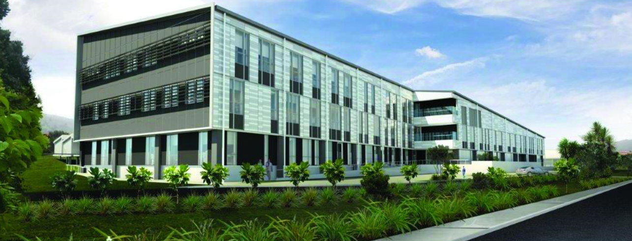
Figure 1: CMM Architects’ computer-generated image of completed buildings
The site consists of two large flat terraces with an elevation difference of approximately 6 m. The new Hospital Building is situated on the lower terrace at approximately 20-30 m distance from a tidal estuary. The IFHC building is located on the upper terrace. The bed of the estuary adjoining the lower terrace is 5 m below the elevation of the lower terrace (Figure 2).
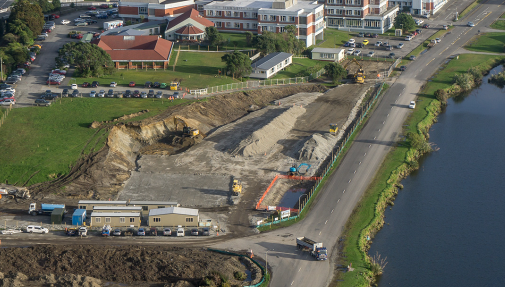
Figure 2: Construction of a building platform at the lower terrace
The new Hospital Building is three storeys high; IFHC is a single storey building. The Site Plan is shown on Figure 3.
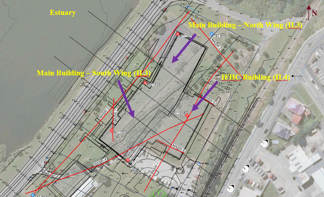
The Hospital Building consists of a north Wing and a South Wing which are seismically separate structures. The North Wing is a three-storey rectangular building with a footprint of approximately 50 m x 25 m. The South Wing is a rectangular building with a footprint of approximately 60 m x 33 m. IFHC building has a footprint of approximately 50 m x 14 m. The Hospital Building was designed as an Importance Level 3 (IL3) structure. IFHC was designed as an Importance Level 4 building. This would mean that the family centre could be used for triage in the event of a very major earthquake, with patients transferred to Christchurch Hospital for critical care, if necessary. The North and South Wings and the IFHC building are connected by corridors but separated by seismic gaps.
- SITE COnditions
Nathan et al (2002) indicate that the site was formed by post-glacial alluvium including river gravel and sand, and swamp deposits. Fill material is present on the upper terrace and at a number of locations on the lower terrace. Stillwater Mudstone bedrock is located at depth. Our geotechnical investigations included multichannel analysis of surface waves (MASW) surveys, boreholes, cone penetration tests (CPTs), trial pits, laboratory testing as well as a topographical survey of the estuary bed levels. Ground conditions encountered during our geotechnical site investigations are summarised in Table 1. The depths of soil layers in Table 1 are given with respect to both the upper and lower terrace ground surface levels. The groundwater table is approximately 2 m below the lower terrace ground surface level.
Table 1: Summary of the ground conditions
| Unit | Depth from upper
terrace (m) |
Depth from lower
terrace (m) |
Layer
thickness (m) |
Soil Description |
|---|---|---|---|---|
| 1 | 0 – 4.7 | N/A | 4.7 | Firm Silt & medium dense sands & gravel; top 1 m – fill |
| 2 | 4.7 – 5.7 | N/A | 1.0 | Soft silt |
| 3 | 5.7 – 8.2 | 0 – 2.5 | 2.5 | Medium dense sand |
| 3A | 8.2 – 9.2 | 2.5 – 3.5 | 1.0 | Loose to medium dense sand (liquefiable) |
|
2 |
9.2 – 11.2 | 3.5 – 5.5 | 2.0 | Soft silt (liquefiable) |
| 4 | 11.2 – 27.5 | 5.5 – 21.8 | 16.3 | Dense to very dense gravel |
| 5 | below 27.5 | below 21.8 | – | Slightly weathered to unweathered mudstone |
The subsoil class of the site is Class C based on the depth to the underlying bedrock. The peak ground accelerations for both buildings, calculated using MBIE Module 1, are summarised in Table 2.
Table 2: Design PGAs for the Hospital Building (IL3) and IFHC building (IL4)
| Design Event | IL 3 | IL 4 |
| SLS 1 | 0.12g | 0.12g |
| SLS 2 | N/A | 0.49g |
| ULS | 0.64g | 0.88g |
- Liquefaction and Lateral Spreading
Our assessment of the investigation data indicated that a sand unit 3A has a potential for liquefaction. A 2 m thick layer of soft silt (unit 2 encountered immediately beneath the liquefiable sand layer is also prone to liquefaction. Both the sand and the silt layers were encountered in the lower terrace at approximately the same elevation as in the upper terrace, with the top of the liquefiable sand layer being at the depth of 2.5 m below the ground surface level at the lower terrace. Some localised silt layers with higher plasticity were assessed as materials prone to cyclic softening. Liquefaction will result in substantial loss of soil strength in liquefiable layers and some subsidence of the ground surface. If pile foundations are used, the top non-liquefiable soil crust located above the liquefiable soil layers, will apply negative skin friction forces to the piles as it settles on top of the liquefiable layers experiencing volume deformation. Our analysis indicated that both building platforms are also prone to lateral spreading. Lateral spreading is expected to occur in the form of lateral displacement of the non-liquefiable soil crust towards the estuary as a result of liquefaction in the subsurface silt and sand layers.
In order to quantify the magnitude of lateral spreading, a slope stability analysis was performed using the computer program Slope/W. The lateral spread displacements were assessed based on the methodology proposed by Jibson (2007). In the liquefied condition, reduced post-liquefaction soil strength as recommended by (Murashev et al., 2014) was used for the liquefiable silts and sands in the slope stability analysis. Post-cyclic softening shear strength was used for localised silt layers prone to cyclic softening; their residual strength was reduced by 20% compared to their static shear strength (Boulanger & Idriss, 2004). The likely ranges of the estimated free field displacements due to lateral spreading based on sensitivity analysis are given in Table 3.
Table 3: Estimated ranges of free field lateral displacement due to lateral spreading
| Design Event | Free Field Displacement (mm) | |
|---|---|---|
| Main Building
(IL3 Structure) |
Integrated Family Health Centre (IFHC)
(IL4 Location) |
|
| ULS | 200 to 500 | 300 to 600 |
| SLS2 | N/A | 150 to 250 |
| SLS1 | 0 | 0 |
The foundation system for the Hospital and IFHC buildings should provide adequate vertical and lateral support to the buildings and resist loads associated with lateral spreading. The main objective of our geotechnical design was to develop a robust and cost-effective foundation system that could satisfy static and seismic performance criteria for the proposed buildings. A number of foundation options were considered, including shallow foundations (intersecting ground beams and rafts), timber piles, driven reinforced concrete and steel piles, steel screw piles, reinforced concrete bored piles, continuous flight auger (CFA) piles. All of the foundation options were considered with and without ground improvement. Ground improvement was considered either within the buildings footprints or beyond the building footprints (i.e. a strip of ground improvement in the area between the estuary and the Hospital Building). Ground improvement options considered included stone columns, rammed aggregate piers, CFA ground improvement piles, deep mixing and high-pressure jet grouting. Given the proximity to the existing operational hospital, construction techniques creating extensive noise and vibration were not acceptable. Based on the comparison of various foundation options, bored and CFA piles foundations were adopted. The pile foundation system can transfer structural loads to deeper, more competent dense gravel layer capable of providing adequate bearing capacity and acceptable settlements. The piles were designed to resist the downdrag loads as well as the lateral spread loads. For analysis of ground improvement options, ground improvement CFA piles were adopted to minimise noise and vibration effects. In this technical paper we discuss adopted design methodology and comparison of piled foundations with and without ground improvement in the form of CFA piles.
- lateral displacement
Given complex interaction between the structural piles and the laterally displacing site soils, it was considered prudent to carry out a finite element analysis of soil-structure interaction using computer program Plaxis as follows:
- The site model was developed based on available survey data, borehole, CPT and MASW information
- Soil parameters for various soil units were assigned based on the available test data; soil layers were modelled using Mohr-Coulomb model
- The soil model was loaded by pseudo-static horizontal volume forces to generate a field of lateral displacement that agrees with the lateral displacements given in Table 3
- Structural piles (with pile caps) of the new Hospital Building were then added to the model and the model was analysed to assess the reinforcing effect of the piles on lateral displacement of the site soils; the displacements were reduced, resulting in reduced bending moments in the piles
- CFA ground improvement piles were added to the model to reduce lateral displacements and bending moments and shear in the Hospital Building piles but could not provide a cost-effective alternative
Distribution of the free field lateral displacements for IL4 ULS event generated in Plaxis model is shown on Figure 4. It should be noted that the Hospital Building (main building) is an IL3 structure and therefore design PGAs and displacements for the Hospital Building are lower compared to those for IL4 ULS event.

Figure 4: Free-field displacement for IL4 ULS event (420 mm to 560 mm displacement at IFHC platform)
Structural RC piles (with pile caps) were then added to the model, and the model was analysed to assess the reinforcing effect of the piles on the magnitude of the lateral displacement of the site soils. The piles used in the model for the Hospital Building were 1.0 m diameter 16 m long RC piles at 8 m spacings embedded into non-liquefiable material (dense to very dense gravel). For IFHC building, 0.6 m diameter 10 m long CFA piles were used. Our analysis indicated that lateral displacements were substantially reduced due to reinforcing effect of the piles (Figure 5). The differential displacement between the toes of the piles and the pile caps were also substantially reduced. Therefore, consideration of soil – structure interaction effects resulted in reduced bending moments and shear in the piles compared to simplified pseudo-static design methods where pile bending moments are calculated by either applying the free field displacements to the piles or to the base of the soil springs.
A strip of CFA ground improvement piles in the area between the estuary and the Hospital Building were added to the model as shown on Figure 6 to reduce lateral displacement but ground improvement was costly and could not provide a cost-effective alternative. The use of stronger structural RC foundation piles appeared to be more cost effective ($2M cost saving) compared to lighter structural foundation piles plus a strip of ground improvement.
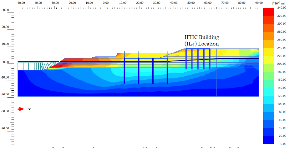
Figure 5: Displacements for IL4 ULS event (235 mm to 245 mm displacement at IFHC platform) with structural piles in model
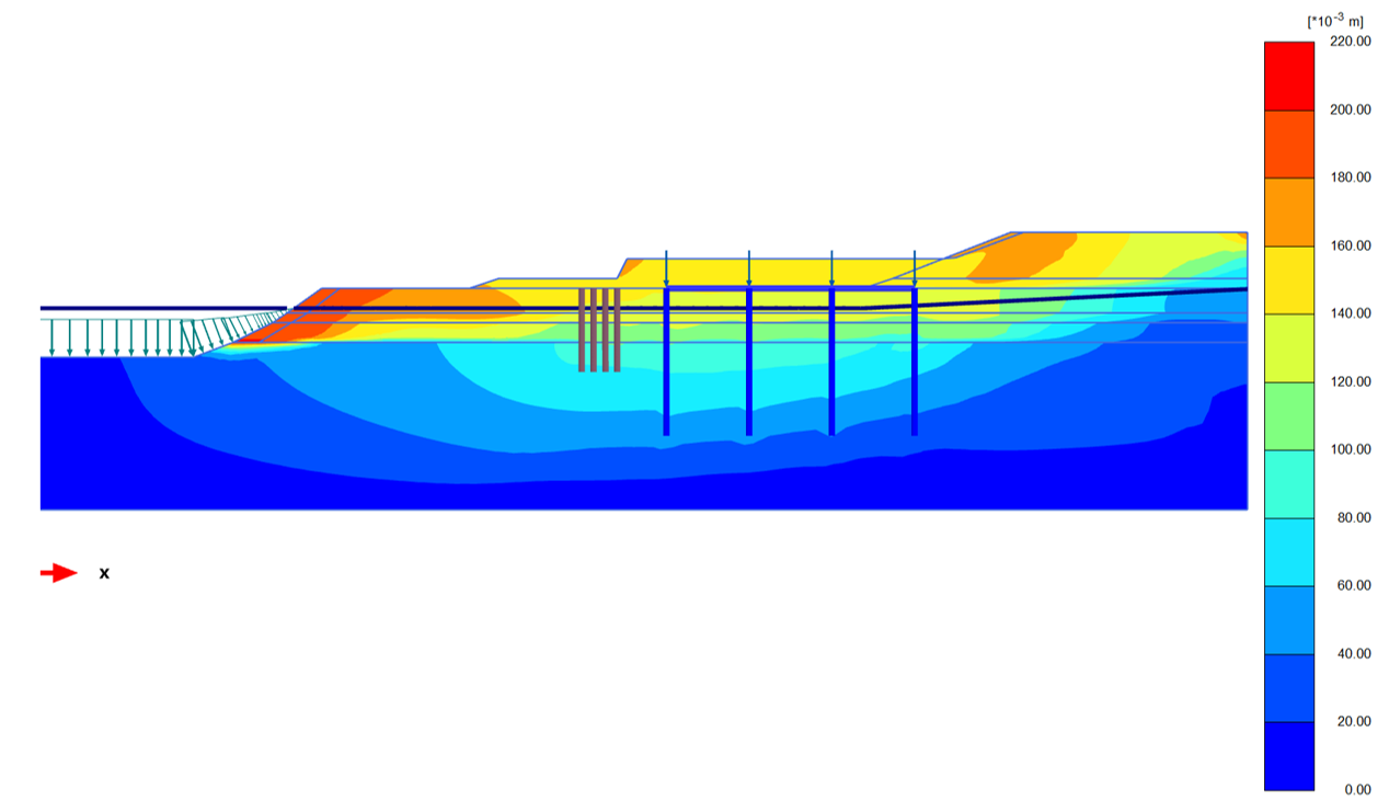
Figure 6: Displacements for IL3 ULS event for the option with CFA ground improvement piles
- Design of piles
The following design procedure was adopted:
- Design the Hospital Building piles by applying the estimated lateral spread displacements from Plaxis model with piles (Figure 5) at the base of the soil springs as required by the pseudo-static design method described in Murashev et al (2014). SAP2000 software was used for this analysis. Bending moments and shear in the piles were also determined from the Plaxis model with piles included and appeared to be close to those assessed in SAP2000 analysis.
- Assess lateral spread displacement at the IFHC building platform using Plaxis model with the Hospital Building piles present but without IFHC building piles. This reduced the lateral displacements at the IFHC Building platform but is reasonably conservative Also, contribution of the IFHC piles to lateral displacement reduction was not substantial due to the flexibility of the piles.
- Use the reduced displacements in the pseudo – static analysis of the IFHC Building piles using SAP2000.
The recommended design methodology for both buildings’ foundations is less conservative than the conventional design method where only free field displacements are used. It should be appreciated that the accuracy of the assessment of lateral spread displacements is low and therefore some conservatism in the design (such as neglecting the reinforcing effect of the CFA piles while designing IFHC) is required to cover this.
NZTA report 553 (Murashev et. al., 2014) recommends considering three load cases for structures founded on soils prone to liquefaction and lateral spreading. Given that the thickness of liquefiable soil layers at our site is not very substantial, the load case with cyclic displacement of liquefied ground was not critical and only the following two governing load cases were considered:
- Pseudo-static analysis without liquefaction where structural inertia loads were applied in the absence of liquefaction or lateral spreading.
- Lateral spreading analysis with substantial degradation of soil’s stiffness and strength and applied kinematic loads (lateral spread displacements). Structural inertia loads are of secondary importance in the spreading phase and in many cases can be ignored. In our analysis, we applied 25% of the structural inertia loads together with lateral displacements.
In the second load combination structural and kinematic loads were applied in accordance with Cubrinovski method as described in Murashev et al (2014) and shown on Figure 7.
Figure 7: Pseudo-static model for piles in laterally spreading ground (Murashev et al, 2014)
1 m diameter RC bored piles were adopted for the new Hospital Building, 0.6 m diameter CFA piles with steel H-pile core were adopted for IFHC building.
- CONSTRUCTION
Construction of the bored and CFA piles was challenging due to the presence of large boulders (up to 0.3 m size) and cohesionless nature of sandy gravels (Figure 8). Construction activities are shown on Figure 9. For the bored piles, a temporary casing was installed to 7 m depth to ensure compliance with positional and verticality tolerances. Polymer was used to stabilise the bored pile shafts below 7 m depth prior to concreting. SPT tests in pile holes were used to confirm the founding strata once the piles were bored to design founding depth. 15 piles had 40 mm diameter hollow steel access tubes installed to allow cross hole sonic logging to be carried out (4 tubes were installed per test pile). The cross hole sonic testing was carried out on completion of the piling works and confirmed good quality of the piles. Construction of all piles was successfully completed by March Construction in early 2018.

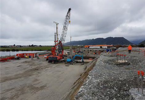

Figure 8: Structural details and construction of the bored piles for the Hospital Building; and large boulders extracted by the auger from a bored pile shaft
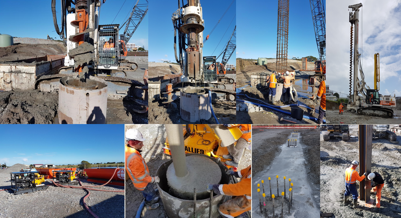
Figure 9: Left to right: Augering, shaft cleaning and installation of casing for bored piles; augering of CFA piles, polymer plant; tremie concrete for bored piles; completed bored piles; installation of H-pile core into a CFA pile
New Hospital and IFHC Buildings are founded on a site prone to liquefaction and lateral spreading. Extensive geotechnical investigations and analysis were carried out to design reliable and cost-effective foundation systems for both buildings.
Soil structure interaction analysis was required to take into account reinforcing effect of the structural piles on ground movement and enabled the designers to reduce kinematic loads on IFHC piles and avoid the use of costly ground improvement. Ground improvement was considered but could not provide a cost – effective alternative to robust structural pile foundations without ground improvement. Avoidance of ground improvement resulted in a $2M cost saving.
- acknowledgements
The Ministry of Health’s Project Manager, Jim Coard is thanked for his understanding of the geotechnical challenges, support of an extensive soil investigation and assessment programme and patience. Support from the Johnstaff project managers (Alistair Burke and Sam Beveridge) and WSP Opus project manager Mark Wilson through the course of the project is highly appreciated. Construction of the pile foundations was completed by March Construction.
- REFERENCES
Ambraseys, N. & Srbulov, M., 1995. Earthquake Induced Displacements of Slopes. Soil Dynamics and
Earthquake Engineering, Vol 14, 59-71, Great Britain.
Boulanger, R.W. & Idriss, I.M., 2004. Evaluating the Potential for Liquefaction or Cyclic
Failure of Silts and Clays. Report No. UCD/CGM-04/01, California: University of California.
Jibson, R.W., 2007. Displacement, based on Regression Models for estimating coseismic landslide
displacement, Engineering Geology 91, 209-218.
Murashev, A., Kirkcaldie. D., Keepa, C., Cubrinovski, M. & Orense, R., 2014. The development of
design guidance for bridges in New Zealand for liquefaction and lateral spreading effects.
NZ Transport Agency research report 553, 142pp.