
Abstract
The Christchurch Northern Corridor is a scheme involving the construction of a new 4-lane highway connecting the City of Christchurch to the Northern Arterial Motorway. The scheme’s site is predominantly underlain by up to 15m of alluvial deposits including very weak, highly compressible peat and organic silt materials, as well as dense sand horizons, overlaying the Riccarton Gravel. These materials are associated with the historic swamp and overbank deposits of the Yaldhurst Member, Springston Formation and are up to 10,000 years old. Of note, the new highway’s southern extent crosses the Cranford Basin: a large and isolated pocket of peat, approximately 5 m deep, overlying interbedded horizons of sand, silt (organic in places) and peat. Since construction began in Early 2017, new embankments and temporary surcharge areas have experienced significant consolidation settlements, bearing capacity failures and heave. This paper provides details regarding (a) risks and challenges associated with constructing on soft peat deposits; (b) adopted mitigations; and (c) the settlement back-analyses undertaken to verify long-term performance.
1 Introduction
This paper presents the risks and challenges encountered during the design and construction phases of the Christchurch Northern Corridor project (CNC), associated with constructing on soft peat deposits which are prevalent throughout the site. The main risks and challenges comprised excessive settlement, inadequate bearing capacity, for both structures and road foundations, and effects of seasonal groundwater variations.
This paper also summarises the back-analysis to show compliance with design specifications and project long-term Minimum Requirements (MRs). This approach involved a robust settlement, deflection and porewater pressure monitoring regime and the back-analysis of the design settlement parameters.
2 Risks and Challenges
Compressible peat and organic silt deposits vary in thickness, consistency, depth and compressibility across the site. The prevalence of this material combined with variable embankment heights and typically high groundwater also made for challenging design and construction. The staging of embankment construction and surcharge fill meant sixty-six (66) distinct earthworks areas were defined, each with their own construction staging and design for settlement mitigation.
2.1 Road Embankment Construction Challenges
2.1.1 Settlement and Groundwater
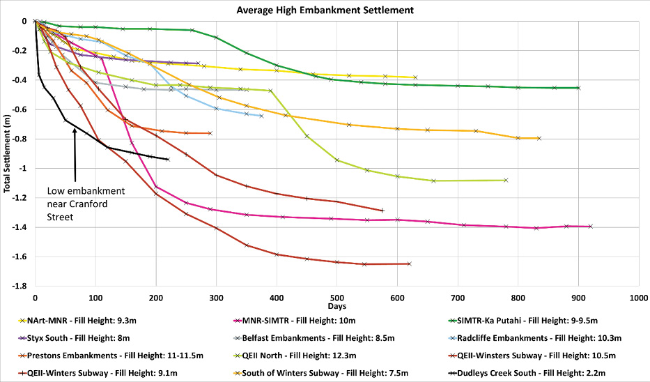
As shown in Figure 1, the averaged total settlement and consolidation time of high embankments varied significantly across the project. The heights presented in Figure 1 are the combined embankments design heights plus surcharge thickness. Most high embankments (4-8.8 m high) settled between 0.6 to 1.6 m with primary consolidation typically complete around 6-12 months. The low embankments (0.5 – 4 m high) settled between 0.1 to 0.5 m, typically performing as per design. However, in discrete locations, residual settlements and post-pavement construction settlement predictions exceeded the MRs. Where reduced, observed and predicted, creep settlements were recorded / predicted, this is believed to be due to the effectiveness of the applied surcharge thickness.
The embankment construction also resulted in lateral movements of soils, which was a significant design challenge around piled structures due to the potential for pile bending due to consolidation.
The largest thickness of surcharge to design embankment ratio on the project of 0.5 was applied to the low embankments around the Cranford Street Southern Tie-In fills, one embankment (as shown in Figure 1) settled 0.95 m with an applied fill thickness of 2.2 m. Heave between 10-30 mm was typically observed across the project following surcharge removal.
Groundwater typically varies between 0.5 to 1.5 m below ground level (bgl) along the alignment. In locations such as the Cranford Basin, groundwater is at ground level. In addition, there are artesian conditions, to sub-artesian at certain locations, at depth, at the top of the Riccarton Gravel. High groundwater and a prevalence of springs made construction difficult and had a notable effect on the settlement of embankments in some areas, particularly in the southern zone of the project. Approaching Summer, as the groundwater level started to drop, the embankment settlement occasionally accelerated, making surcharge back-analysis more difficult and causing programme delays.
2.1.2 Bearing Capacity Failure
The Cranford Basin has up to 5 m of highly compressible peat and organic silt with little to no stiff crust to provide bearing resistance to embankment loading. For each of the Cranford Tie-In embankments the settlement was 25% to 50% of the placed fill thickness including surcharge. This typically resulted in bearing capacity and global stability failure of the embankments as shown in the photos in Figure 2. This occurred despite the rate of filling being generally controlled. The undrained shear strength of these soils was back-calculated to be as low as 5 kPa.

2.2 Network Drainage Construction Challenges
The project has ten major cross culverts including three large post-tensioned box culverts and many network drainage lines, at or below existing ground level. The main risks associated with these structures included differential settlement between the structure and the embankment and construction on soft soils and below groundwater level. In areas worst affected by compressible soils, such as the Cranford Basin, minor structures such as manhole chambers, culvert head walls or drainage lines, recorded settlements of 50 – 125 mm, even where little net load was applied to the foundation soils. These settlements were likely due to primary consolidation as these occurred generally within weeks.
2.3 Survey Monitoring Control Points
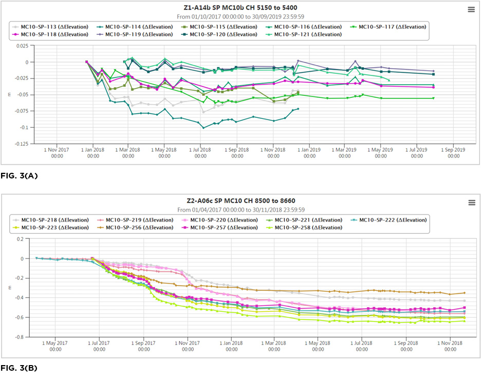
One of the biggest challenges to the project was the consistency of settlement monitoring survey data. Though control point calibration was undertaken regularly, the movement of control points often resulted in variability in the data, fluctuating as much as 20-40 mm, outside of an adopted survey tolerance of ±5mm. This made it challenging to assess trends and provide settlement predictions for low embankments with small total settlements (as shown in Figure 3A).
For embankments in the Cranford Basin, large fluctuations created uncertainty as to the completion of 90% primary consolidation and compliance with the MRs (as shown in Figure 3B). This caused programme delays during the approval process for surcharge removal.
3 Mitigations
The design and construction challenges on the CNC project required innovative engineering solutions, methodology changes and at times a risk-based approach to decision making. This section outlines the mitigation solutions for the risks and challenges presented in Section 2.
3.1 Road Embankments and Construction Challenges
3.1.1 Settlement and Groundwater
To mitigate settlement risk, settlement analyses were completed for all earthwork areas and where required, surcharge and wick drain schemes were designed. Laboratory testing and trial embankment data were used to derive settlement parameters during design. As the project progressed, the parameters were refined by back-analysis based on the actual embankment performance, as design settlement predictions both over and under-predicting the actual field settlements.
During construction, back-analysis was undertaken to assess compliance with the project’s MRs for each earthworks area before surcharge was removed and to extend the surcharge hold period if necessary. This approach is outlined in Section 4. In addition to the MRs, the CNC Alliance instated a 2-month ‘Pre-Paving Hold Period’ so that the effectiveness of the surcharge could be confirmed, or additional action taken if settlement was still on-going.
In some locations, the back-analysis of surcharge could not prove compliance with the long-term settlement MRs; for these areas a risk-based approach was adopted. The Project Alliance Board (PAB), consisting of Alliance partners and clients, reviewed risk assessments comparing the consequences of the predicted ongoing settlement, against the costs and risks of potential mitigation measures. For some areas, it was concluded that there was little benefit in maintaining the surcharge. For other areas, evidence of significant creep settlement meant that the reputational risk and expected damage to infrastructure outweighed the programming and project cost implications. Therefore, in these areas, the surcharge hold period may have been extended by several months to reduce the risk of long-term settlement.
The consequences of ongoing total and differential settlement to the road safety and performance ranged from loss of road crossfall, reducing the effectiveness of the network drainage, to damage to kerbs, barriers, pavement and ride quality.
To mitigate the effects of groundwater and excess pore pressure build up, wick drains were installed to 7-8 m bgl at 1.5-2 m spacings in areas where soft and compressible cohesive soils were present and where the programme for construction was relatively short. In several locations where wick drains were not installed, such as the Cranford Basin, increased settlement duration and potential non-compliance with long term settlement MRs were observed due to slower than expected pore-pressure dissipation.
3.2 Network Drainage
To mitigate the risk of total and differential settlement of cross culverts and network drainage lines, a risk assessment was completed across the project for every individual pipeline. A combination of ballast raft construction and/or surcharging of pipe alignments was implemented as required to mitigate long-term settlements. Surcharging was undertaken by excavating the trench and placing the pipe foundation so that the heavier trench backfill was in place for the surcharge period. Once the settlement had slowed the trench was re-excavated to lay the pipe, and the backfill replaced. Pipe trench settlements exceeding 150 mm were observed just due to the net increase in weight of the trench backfill, with no fill placed above original ground level. The success of this methodology will be proven with time, however, as discussed in Section 2.2 in locations where infrastructure was constructed outside of the alignment and were not surcharged, much greater post-construction settlement was observed than surcharged sections. Pipe rafts were not observed to reduce total pipe settlements, although they did mitigate differential settlements and provide a stable base for the pipe to be laid on.
For major culverts along existing drainage lines, ballast rafts and temporary corrugated steel culverts, to be subsequently replaced with permanent culverts, were installed prior to embankment/surcharge filling. The temporary culverts deformed significantly due to the embankment settlement and construction loading. This made it difficult to assess the true culvert settlement and to determine whether the risk of long-term differential settlement had been effectively mitigated.
Piled culverts were avoided as they would result in localised differential settlements either side of the culvert, resulting in poor ride quality and drainage inefficiency due to any ongoing settlement. The permanent culverts were over-sized, so that they could settle with the road embankment while still maintaining sufficient capacity and ride quality. As a secondary mitigation, to reduce the effects of differential settlement at culverts, two layers of geogrid were installed in subgrade and pavement layers at the transition between embankment fills and fills over some major culverts.
3.3 Survey Monitoring Control Points
Approximately midway through the project, following issues with consistency in monitoring results, a mitigation measure was implemented to improve accuracy of readings. The original control points which were installed in a range of locations near the embankments, from ground points to ancillary structures generally founded at existing ground level, were replaced by UC steel piles installed into dense sand layers around the site. There has been no quantitative assessment comparing the accuracy of monitoring before and after the control point upgrade, however, from a qualitative perspective, there was a clear reduction in large monitoring fluctuations that had been hampering the project.
4 Compliance and Long-Term Performance
The MRs, defined to assess satisfactory behaviour, focused on long-term ground displacements and degree of consolidation. Limits were specified in the MRs and are summarised in Table 1. To verify compliance with the MRs, a back-analysis supported with numerical verification was adopted by the following methodology:
- Settlement, deflection and porewater pressure monitoring.
- Back-analysis of design soil parameters.
- Long-term settlement prediction against MRs (based on back-analysed soil parameters).
Table 1: Minimum Requirements (MRs) adopted in the CNC project.

Long-term settlement prediction was undertaken considering two distinct analysis methods to provide robustness and confidence to the predictions: 1) Terzaghi’s one-dimensional consolidation theory, assuming that primary and secondary consolidation settlements occur separately; and 2) a non-linear consolidation method, assuming that primary and secondary consolidation settlements occur simultaneously. The results of these assessments were independently peer reviewed.
This approach provided a robust risk-assessment based on real-life, site-specific data. Despite some challenges regarding monitoring accuracy, as discussed in Section 2.3, it is considered that this approach was successful. It allowed the key stakeholders to evaluate the risks and identify when mitigation measures were required, resulting in significant overall risk reduction.
5 Conclusion
The soft, compressible peat deposits underlying much of the CNC alignment presented challenges manifesting in low bearing capacities of embankment foundations, excessive construction and consolidation settlement, and excessive movements of structures and foundations.
These challenges were overcome via ground improvements in the form of embankment surcharging, use of basal geogrid, wick drains and raft foundations.
A robust back-analysis and verification process was adopted to assess the effectiveness of the adopted mitigation measures and extend or reduce the surcharge periods where required.
It is considered that the mitigation measures adopted, verification analyses and on-site control mechanisms, enabled the successful delivery of a major highways scheme underlain by variable and challenging ground conditions.
6 Acknowledgements
The authors would like to acknowledge the contribution of Waka Kotahi and the CNC Alliance in the provision of the design and construction information presented in this paper.
7 References
CNC Alliance (2017). “Embankments Zone 2a Design Report”. CNC-2-G-AA04060-RP-0027 Rev C. Contract NZTA 63177. Christchurch Northern Corridor. April 2017.
CNC Alliance (2017). “Settlement Back-Analysis Philosophy Memorandum”. CNC-4-G-AA01155-RP-0080 Rev A. Contract NZTA 63177. Christchurch Northern Corridor. September 2017.
Trimble. (2019). Trimble 4D Control. Westminster, Colorado, USA.