Keywords: Geogrid, Geosynthetic, Bridge Abutment, GRS Design, Bridge Foundations
Abstract
This study investigated the performance of geogrid reinforced bridge abutments for their use in New Zealand. Over the past couple of decades geosynthetics, and geogrids in particular, were employed to create a reinforced soil block that supports the bridge superstructure and resists lateral earth pressures, especially seismic actions. Many geogrid reinforced soil abutments were built overseas and they have performed very well, especially during large seismic events. In New Zealand these structures are not prevalent.
This study will review international case studies from the past two decades to draw out design and construction considerations and potential advantages. A key focus will be on the seismic performance of geogrid reinforced abutments, including seismic performance in past events derived from long term monitoring and large-scale laboratory testing.
This study then reviews current international design best practice and compares it to New Zealand’s design approaches for geogrid reinforced abutments in the context of Waka Kotahi’s Bridge Manual. Roadblocks to wide-spread implementation on New Zealand’s roading network are discussed and potential changes to current design guidance are suggested.
1. Introduction
This study examines the use of geogrid reinforcement in bridge abutments. While these structures are common overseas, and exhibit very satisfactory performance, they are not frequently used in either New Zealand or Australia. This study was initiated on the question ‘Why are these structures not more prevalent in New Zealand?’
This paper will review case studies and design approaches used internationally, including the use of these structures in high seismic environments. The second part will describe current best design practice and explore the potential integration into New Zealand design practice.
2. Bridge abutments
(Structure, Components and Parts 2020) defines key elements of bridge structures, namely:
- Superstructure: mounted on the substructure and includes decking, girders, slabs, cable stays or suspended systems that collect the traffic loads.
- Substructure: comprises piers, abutments, bearings and all components collecting actions from the superstructure and transferring those into the foundations;
- Foundations: which transfer the weight of the bridge and any loads on it to a competent bearing strata;
Figure 1 sets out their relationship to each other.
Figure 1 Components of a bridge
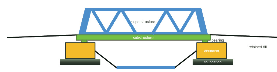
This study concentrates on bridge abutments, as they collect and resist lateral actions, deformations and imposed stresses. Those actions originate from the soil that forms part of the approach fill and vertical loads from the superstructure, including the bridge self-weight and traffic loads. Abutments are connected to shallow or deeply embedded foundations, (Rajapakse 2016). Abutments must be stiff to resist imposed loads and deformations, and to transfer those to the foundations. The performance of an abutment is integral to the overall performance of a bridge, (Wilson and Tan 1990) and (Wood 2015). Abutments are generally earth retaining structures and can be made from a monolithic block of reinforced concrete or comprise soil bodies with or without facing elements to retain the fill.
3. Geogrid reinforced soil abutments
Geogrid reinforced soil [GRS] abutments are bridge abutments comprising interlayered granular soil and geogrid materials.
In recent years, applications of the GRS technology for bridge-supporting structures have gained increasing attention on the international stage. Depending on the facing rigidity, GRS bridge-supporting structures can be grouped into two types: “rigid” facing and “flexible” facing structures. A “rigid” facing is typically a continuous reinforced concrete panel, either precast or cast-in-place, connected to geogrid reinforcements using a full-strength coupler or bodkin joint. A “flexible” facing, on the other hand, typically takes the form of wrapped geogrid, dry-stacked concrete modular blocks (segmental block wall), timber, natural rocks, or gabions. In contrast to a “flexible” facing, a “rigid” facing offers a significant degree of “global” bending resistance along the entire height of the facing panel, and thus offers greater resistance to “global” flexural deformation caused by lateral earth pressure exerted on the facing, (NCHRP Report 556 2006).
Since 1994, the Japan Railway has constructed a large number of full-height concrete facing GRS bridge abutments and piers, (Tateyama, et al. 1994), (Kanazawa, et al. 1994) and (Tatsuoka, Uchimura, et al. 1997) using a rigid wall GRS system developed by Tatsuoka and his associates at the University of Tokyo. These GRS bridge-supporting structures were constructed in two stages. The first stage involves constructing a wrapped-face GRS wall with the aid of gabions, and the second stage involves casting in-place a full-height reinforced concrete facing over the wrapped face and connecting it to the gabions with small anchors. Field measurement has shown that these structures experienced little deformation under service loads and performed far better than conventional reinforced concrete retaining walls and abutments during the 1995 Japan Great Hansin earthquake that measured Mw7.2, (Tatsuoka, Uchimura and Tateyama 1997), or VIII on the Modified Mercalli Scale. GRS bridge-supporting structures with a flexible facing have been the subject of several studies that will be discussed in the following sections. These structures were investigated as they have shown great promise in terms of ductility, flexibility, constructability, and cost, but also because they feature decades of operational performance with no signs of distress, and on some occasions have been subjected to high intensity earthquake shaking.
(Koerner 2012), (Detert and Thomson 2013) and (Zornberg, et al. 2018) describe the history of using GRS in bridge structures in the United States and Europe which started approximately 25 years ago. GRS was used initially in the construction of the front face and wingwalls of bridge abutments, while the abutment itself was supported on separate conventional rigid foundation systems, often deep piles, refer to Figure 2a). An alternative application was developed to isolate the rigid components of the abutment from horizontal earth pressures generated by the backfill. This is achieved by leaving a gap between the back of the rigid abutment wall and the GRS. The gap could be left open or filled with compressible material, refer to Figure 2b). Over the past two decades attention has turned to supporting superstructures directly upon a specifically designed GRS. The deck loads are transmitted via bearings or foundations directly onto the GRS and through the GRS to the competent native soils, refer to Figure 2c).
Figure 2 Configuration of geogrid reinforced soil in bridge abutments, (after Detert et al 2013)
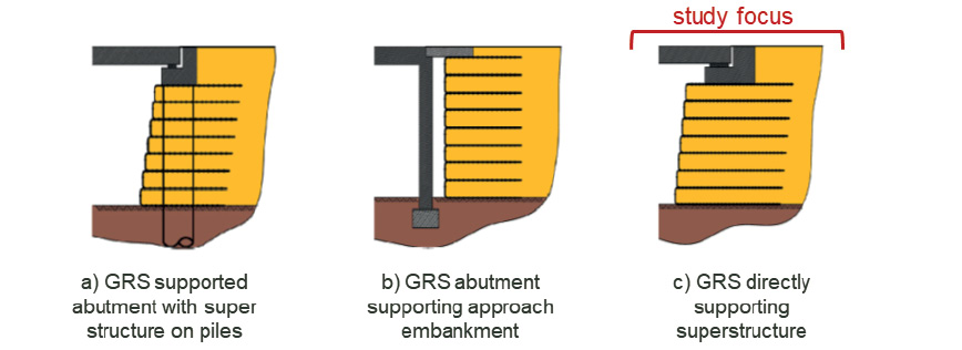
In this study, the GRS abutments are implemented without construction of conventional rigid foundation systems such as deep pile foundations. Such systems are variously termed in publications but are referred to in this paper as GRS abutments.
Design considerations include contact pressures between the bearing or bank seat, which are relatively low, under normal operational conditions; typically in the range of 150 to 250 kPa, (Kessel van and Hangen 2015). The bearing or bank seat is typically located at a setback of about 1.0m from the edge of the facing and at the top of the GRS. Due to the concentrated load, the reinforcement is more closely spaced directly underneath the bearing / bank seat, typically with 200mm to 300mm vertical spacings, as opposed to the main soil body where the main reinforcement spacings is 450mm to 600mm apart.
Rigid or flexible facings can be provided to the GRS abutment, and a variety of geogrid reinforcement types are possible which may have constant or varied spacing within the GRS and be of uniform or varied strength and length within the abutment. As with normal earth retaining structures, reinforced concrete panel walls connected to geogrids can create GRS abutments with ‘rigid’ facings. Facings such as smaller individual concrete panels, modular blocks, or wrapped-around construction are considered ‘flexible facings’; with increasing degrees of flexibility, respectively, (FHWA 2015).
Bridge structures may be integral i.e. where there is no provision for expansion joints between the superstructure and the approach embankments. Alternatively they may feature separation joints between the bridge superstructure and sub-structure.
In summary, this paper solely refers to geogrid reinforced soil abutments, mostly using uniaxial geogrids, where the bridge superstructure is directly supported on the reinforced soil block.
4. Geogrid reinforcement
Prior to turning to case studies it is important to understand how geogrids work in soil and what composite behaviour they establish in it. In general, reinforced soil or mechanically stabilised soil are combinations of alternating layers of compacted earth fill with relatively closely spaced tensile reinforcement elements to create an earth composite structure, whose properties and performance depend on the interaction between the soil and the reinforcement. The reinforcing elements may be metallic, polymeric or even natural materials, and may take the form of sheets, rods or grids.
A number of terms are used in published literature to describe reinforced soil systems, a common term in New Zealand is MSE (mechanically stabilised earth), which can include metallic and polymeric reinforcements in various forms such as straps, grids and meshes. In this paper, only Geogrid Reinforced Soils (GRS), a special subset of geosynthetic reinforced soils systems that use layers of polymeric grids, is being investigated.
Geogrids may be constructed from polyester [PET], polyvinyl alcohol [PVA], polyethylene [PE] or polypropylene [PP]. Geogrids can be divided into uniaxial, biaxial and more recently triaxial grids. Uniaxial geogrids have one principal orientation and are significantly stronger in one direction. They are usually employed in earth structures where ‘plane strain’ conditions persist. Biaxial geogrids feature equal strength in two orthogonal directions and are usually used in horizontal applications such as load bearing pads, pavements or load transfer platforms. Triaxial grids have three in plane directions and were primarily developed for pavement reinforcements. This study focuses on uniaxial geogrids as they are the main reinforcement elements for reinforced soil abutments.
4.1 Elastic-viscous-plastic behaviour
Geosynthetics, and geogrids in particular, are tested in air (characteristic tensile strength or long duration creep tests), but their performance in air [under normal laboratory tensile test conditions] is very different to their working conditions once they are embedded in competent engineered fill materials, (McGown and Kupec 2001), (Kupec and McGown 2004) and (Kongkitkul, et al. 2004).
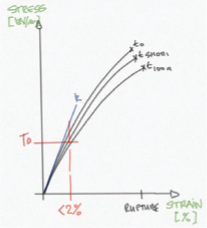
Their elastic viscous plastic (creep) behaviour was often stated as an adverse material behaviour, but creep characteristics determined in laboratory testing (in-air) are very different once soil and geogrid are working together, (Kupec 2004). Further, modern geogrids, developed over the past two decades for use in Earth Structures, feature a high initial stiffness and a low creep tendency at their operational strain levels, usually around 1 to 2% upper bound design strain levels, i.e. a fraction of their ultimate tensile strain capacity, refer to Figure 3. Long term strains measured insitu in monitored Earth Structures exhibit less than 0.2% to 0.5% strain development under normal operational conditions.
Figure 3 Isochronous stress strain curves [tx] showing high initial stiffness [k] and low creep susceptibility at operational strain levels and design strength [TD]
In summary, practitioners and designers may not fully account for the in-soil behaviour of geogrids once they form a composite with the soil. Elastic-viscous behaviour should be positively attributed as it shows a very high capacity to take short term actions like earthquakes or accidental over load, (Tatsuoka, Uchimura, et al. 1997) and (Kupec 2000).
4.2 Confinement
The composite behaviour between granular soil and geogrid reinforcement relies on interaction between both materials. This is because it requires strain compatibility (large deformations in load supporting structures like pavements and very small deformations in earth structure applications such as retaining walls or abutments), (Uchimura, et al. 2004). In geogrid reinforced soils, stability is achieved by lateral support of soil particles enabling significantly higher vertical (axial) stresses to be carried. The reinforcement resists the stresses in tension, a mechanism termed “confinement”, refer to Figure 4.
Figure 4 Effect of confinement on increasing axial load bearing capacity

4.3 Dynamic interlock
(McGown, Yeo, et al. 1990) identified in the early 1990s that ‘dynamic interlock’ induced by compaction stresses or repeated dynamic actions (such as traffic loading) significantly enhances the performance of geogrid reinforced granular soils. Later studies using transparent granular soil (fused quartz in mineral oil) at the Geoengineering Centre at the Royal Military College in Kingston, Canada, demonstrated the previously postulated interactions of geogrids with granular soils. It was confirmed that geogrid interacts differently with soil than purely frictional inclusions, such as sheets or strips, e.g. steel strips and strap reinforcement, (Fawzy and Bathurst 2014). This finding is important to distinguish between purely frictional interactions, which are usually found with metallic reinforcements such as Reinforced Earth™ or Terra Armée™ systems, and geogrids where composite action is achieved with confinement and dynamic interlock.
Dynamic Interlock is created by the applied loads causing lateral movement in the soils in contact with the geogrid, which in turn cause tension forces to develop in the geogrid. Tension forces are generated by frictional contact and interlock with the geogrid apertures, (Peng 2017). Stiffness of the reinforced fill (backfill) is increased by interacting with the geogrid, which in turn is a direct function of the stiffness of the geogrid. Thus, strain compatibility of the soil and geogrid is critical to the overall performance of the structure, (McGown, Yeo, et al. 1990). Further studies at the University of Strathclyde indicated that geogrids achieve greater stability by pre-tensioning through the soil, which is also observed as a reduction in creep, (Kupec and McGown 2001) and (Kupec 2000). This tensioning effect was studied by Japanese researchers at the University of Tokyo, (Uchimura, et al. 2004) and is now widely used in the construction of reinforced earth structures in Japan by vertically prestressing GRS abutments.
The composite behaviour explains why GRS structures, including abutments, outperform traditional retaining structures that rely on resistance of earth pressures alone. Composites often behave differently to their individual components and only provide different material properties in combination. Glass fiber reinforced plastics, or reinforced concrete, are some engineering composites where the combination of material properties create new, and often surprising, characteristics.
5. Global use of GRS abutments
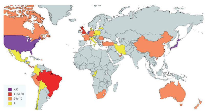
Figure 5 shows the global distribution of locations where GRS abutments have been implemented over the past two decades, (Detert and Thomson 2013). Regions where GRS abutments are most prevalent are the United States, Northern Europe, and Japan. GRS abutments feature heavily in seismically active areas, including Japan and the West Coast of the United States.
Figure 5 Global distribution of GRS abutments, countries standing out are USA, The Netherlands and Japan, followed by Brazil and the UK (correspondence with G Stevens)
As the prevalence of gravity loaded GRS structures has increased, several design approaches have been developed for GRS structures that only support lateral earth pressures. These include specific design methods for GRS abutments. In the USA, where GRS abutments have been most frequently used in roading and highway construction, a significant volume of research has been carried out under the National Cooperative Highway Research Program (NCHRP) by the Transportation Research Board of the United States of America in developing appropriate design methodologies for GRS abutments, (NCHRP Report 556 2006).
The various studies conducted by NCHRP have included
- Literary reviews and summary of research studies,
- Summary and evaluation of state-of-the-art practices,
- Large scale instrumented structures,
- Centrifugal models,
- Evaluation and re-evaluation of field monitoring data,
- Inspection of as-built structures under normal service conditions and following seismic events,
- Numerical analyses.
NCHRP investigated the use of GRS abutments to develop design and construction guidelines for GRS abutments subject to self-weight and loading from the bridge structure. The study considered static ground conditions only. The results are presented in NCHRP Report 556 published in 2006, (NCHRP Report 556 2006). A subsequent round of studies, considered design guidelines for GRS abutments subjected to seismic loads to expand the guidelines from Report 556 to include seismic forces, (Helwany, Wu and Meinholz 2012).
More recent studies by the NCHRP detailed in NCHRP 24-21 (2018), investigates design refinements that can be incorporated into GRS and GRS abutment design processes, and defines a distinction between widely and closely spaced GRS structures, (US Department of Transportation 2018).
The NCHRP studies are considered progressive, rigorous and comprehensive, and the developed guidelines for design and construction are directly relevant to practice in New Zealand. Selected aspects of the studies are discussed in greater detail in the subsequent sections of this paper.
Several published documents are currently available from the NCHRP with regard to the design and construction of GRS abutments, (Helwany, Wu and Meinholz 2012) and (State New York Dep of Transportation 2015).
In 2018 the US Department of Transportation Federal Highways Administration published Design and Construction Guidelines for Geosynthetic Reinforced Soil Abutments and Integrated Bridge Systems which references these studies, with particular emphasis on recent investigations, into better understanding aspects of the composite behaviour such as the effect of vertical spacing of the geosynthetic reinforcement, (US Department of Transportation 2018).
6. International Case Histories
The case histories in this chapter were selected to represent international case studies of design and construction best practice for GRS systems used to support bridge structures, including bridge abutments and piers. The case histories present the evolution of GRS abutments and their increasing breadth of applications on infrastructure projects. The selected case histories include flexible and rigid facings, as well as a varying range of geogrid reinforcement being used. Case histories 7 to 9 focus on GRS structures in seismically active regions and their performance in strong and long duration earthquakes. Overall, the case histories demonstrate benefits to the use of GRS abutments in comparison to conventional structures which include:
- Space saving through construction of near vertical slopes;
- Simple and efficient construction techniques;
- Ability to tolerate relatively large deformations without distress;
- Outstanding seismic performance, (Zheng, et al. 2017) (Morsy and Zornberg 2017);
- Lower cost than traditional walls (reinforced concrete), after (Helwany, Wu and Meinholz 2012) and (Zornberg, et al. 2018).
- Very low rate of failure, generally directly attributed to incorrect material specification of reinforcement and backfill
Case History 1 – Founders / Meadows Bridge, United States
The Flounders / Meadows Bridge was constructed in 1999 and was the first major highway bridge in the USA to use GRS abutments (see Figure 6). The bridge is a two-span road overbridge structure and the abutments are 4.5 metres and 5.9 metres high, (Bathurst 2014).
Figure 6 View of completed Founders / Meadows Bridge and approaches, Colorado, USA, after (Zornberg, et al. 2018)

Both the bridge abutments and the approach embankments are supported by GRS. The GRS abutments have been constructed from angular crushed stone fill with uniaxial geogrids at 400mm spacings and a flexible facing of segmental blocks mechanically connected to the geogrids. The GRS is supported on competent bedrock. The separation between the edge of the footing and the interior face of the wall is approximately 1.35 m (see Figure 7). The tensile strength of the geogrids ranges from 40 to 160 kN/m with higher (tensile) strength geogrid layers used beneath the bridge footings than within the backfill material. The vertical foundation walls are backed with a layer of polystyrene to reduce lateral earth pressures on the facing. A drainage system is incorporated into the backfill.
Figure 7 Typical cross section showing abutment and approach embankment, after (Zornberg, et al. 2018)

Numerous studies report on monitored displacements during construction and creep deformations post construction, (Abu-Hejleh, et al. 2002), (Abu-Hejlah, et al. 2000), and (Bathurst 2014).
The Colorado DOT made the following recommendations for design and construction of
GRS abutments:
- The foundation soil for these abutments should be firm enough to limit the post-construction settlement of the bridge sill to 75 mm.
- The designer should plan for a bridge sill settlement of at least 25 mm caused by the bridge superstructure loads.
- The maximum tension line needed in the internal stability analysis should be assumed bilinear, starting at the toe of the wall and extending through a straight line to the back edge of the bridge sill at the mid height of the wall, and from there extending vertically to the back edge of the bridge sill.
- Ideally, construction should take place during the warm and dry seasons.
- The backfill behind the abutment wall should be placed before the girders.
Take out: Geogrid reinforced abutments performed satisfactorily over several decades showing no adverse effects or any structural distress.
Case History 2 – Maringa Railway Line Bridges in Brazil
In this case GRS was used to support the side walls of an excavation for a railway corridor. Four, at grade, single span road over rail bridges were then constructed across the excavation with the abutments bearing upon the GRS, refer to Figure 8. The abutment heights range from 8 to 9 metres, (Brugger, Gomes and Conte 2012) and (Da Silva, Brugger and Engenharia 2012).
Figure 8 Cross sectional layout of PVA geogrid reinforced bridge abutment, after (Da Silva, Brugger and Engenharia 2012)

The GRS was constructed on native soil deposits. The sidewalls of the trench were constructed using fine grained fill material with layers of geogrid reinforcement at 400mm to 600m vertical spacing. The vertical spacing of the geogrids was closer below the bearing seat, becoming more widely spaced with depth. A polyvinyl alcohol (PVA) type geogrid was used with tensile strengths ranging from 110kN/m to 200kN/m. The lower strength geogrid was used in proximity to the underside of the bridge bearing seat (foundation). Flexible facings were installed consisting of gravel filled hollow segmental blocks with the connection between the geogrid and the blocks maintained by friction. The geogrid was also wrapped against the facing and into the next layer. The separation distance from the bearing seat (foundation) and the interior of the facing ranged from 0.5 to 1.5 metres.
Note that the reinforced soil block is significantly smaller than the Founders/Meadow Bridge, recognising the lack of deformation in the reinforced backfill wedge behind the bank seat.
Take Out: Past research and monitoring of existing structures enabled optimisation of the reinforced soil block geometry and reinforcement layout (lengths, spacings and geogrid strength)
Case History 3 – Ilsenburg Bridge in Germany
Ilsenburg Bridge consists of a single span road bridge constructed in 2000 over the River Ilse and was the first bridge in Germany to use GRS abutments. The bridge was heavily instrumented and monitored for more than a decade, with numerous reports providing long term performance information, (Herold 2002), (Herold 2005), (Herold 2006) and (Herold, Aydogmus and Sander 2008). The abutments are 2.7 metres high.
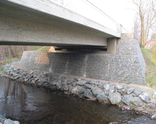
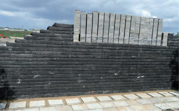
Backfill consists of recycled crushed concrete, with layers of geogrid at 350mm spacing beneath the bearing seat. The geogrid was a polyvinyl alcohol geogrid, with a tensile strength of 140kN/m manufactured by Fortrac. The facing of the GRS abutment consists of stone filled gabion baskets which are mechanically connected to the geogrid (see Figure 9). The bearing seat was constructed at a setback of 1.6 metres.
Figure 9 View of the geogrid reinforced bridge abutment of gabions (flexible facing), after (Herold 2006)

The performance of the GRS abutments was monitored by instrumentation consisting of vertical inclinometers installed to measure horizontal deformations of the abutment, and settlement gauges installed in the bridge superstructure, bearing seat, and abutment wings. The maximum reported horizontal deformation measured after 5 years was 0.2mm, while the maximum settlement recorded at the surface of the abutment, was 4.5 mm, likely due to the compressible subsoil strata. The bridge was subjected to static and dynamic load testing after two years in operation, (Herold 2002), with lateral earth pressures being monitored.
Take Out: Long term performance is equal to conventional abutment structures with creep deformation being low and not affecting the long-term performance
Case History 4 – Venlo Bridges in the Netherlands
The Venlo Bridges are two parallel single span road bridges in the Netherlands which were constructed in 2011 on GRS bridge abutments. The height of the abutments is 10m for one bridge and 7.4m for the other with a 31m span (Van Duijnen, et al. 2012).
The bridges span a low-lying area. A vertical face (supported using GRS) was constructed on one side of the low ground area while the ground in front of the other abutment was sloped at a conventional angle such that GRS was not required for both sides of the bridge.
Backfill to the GRS abutments consists of crushed recycled materials, interlayered with two high strength geogrid reinforcements (increasing in strength in proximity to the bearing seating) at 500mm spacings. Polyvinyl alcohol [PVA] geogrids with a tensile strength of 400kN/m and 200kN/m were used. Modified gabion bags were used for the facing.
In line with Japanese practice for railroad abutments, (Tatsuoka, Uchimura and Tateyama 1997), the GRS abutments were preloaded for a period of two months prior to construction of the bearing seat to reduce long term creep. The performance of the GRS abutments was monitored during the preloading by settlement monitoring of the top of the abutment and the base of the GRS wall. Following installation of the bearing seat and superstructure vertical and horizontal deformations were measured and resulting settlement was mainly attributed to subsoil compression, (Detert and Thomson 2013).
(Van Duijnen, et al. 2012) describes the monitoring of the Venlo Bridges in detail. Figure 10 shows the location of the monitoring points on each abutment and photographs of the bridge during the surcharge and on completion of construction.
The Venlo Bridges monitoring showed that post-construction deformations can be controlled and reduced to only account for the compressibility of the subsoils.
Take Out: Post construction deformations, even for flexible facing systems, can be effectively controlled and reduced further by surcharging.
Figure 10 A Venlo Bridge abutment with flexible wrap around facing, showing concrete block surcharge to control post construction settlement, after (Huesker 2012)
Case History 5 – Nagoya Bridge in Japan
Constructed in the early 1990’s, the single span Nagoya Bridge supports the Japanese Bullet Train passing over a roadway at Nagoya Station, (Kasugai and Tateyama 1992). The bridge abutments are 6 metres in height. The structure was the first example of structures that are now common on the bullet train network with the main design characteristics of high seismic resilience and low maintenance.
The GRS abutments were constructed from well graded gravel with vinyl chloride coated vinylon geogrid reinforcement at 0.3 metre vertical spacings. The tensile characteristic strength of the geogrid was 60kN/m. The setback of the bearing seat was approximately 300mm to 500mm and a gabion wall interior facing was constructed with the geogrid wrapped around the gabions. To meet maintenance requirements and add seismic resistance, a full height rigid concrete wall was constructed against the gabions anchored into the reinforced soil block.
Take Out: Japan implemented highly resilient designs on single span bridges, providing an environment for further development of this technology.
Case History 6 – New South Wales Bridge in Australia
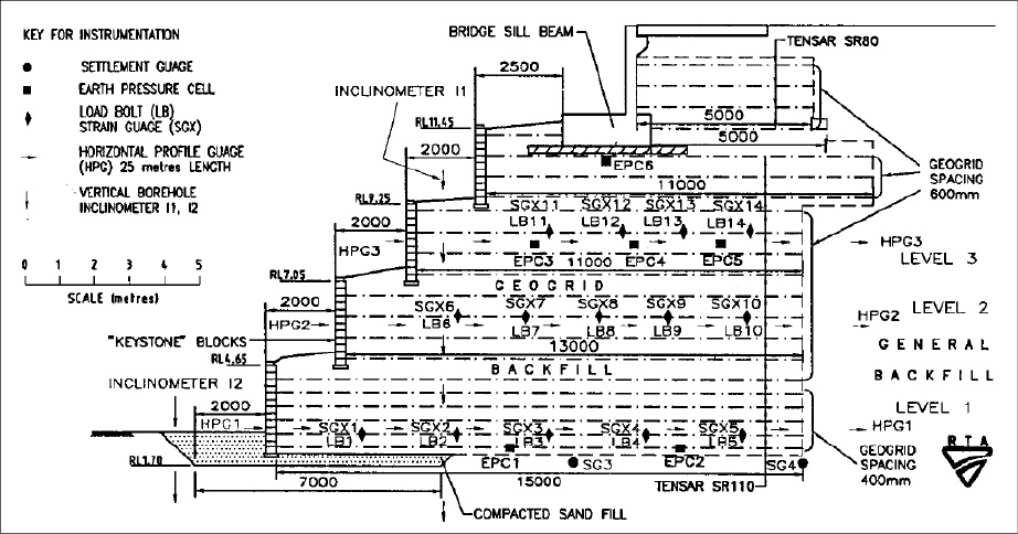
The New South Wales Bridge is a nine-span road bridge on the Pacific Highway which spans the Tweed River. The bridge was constructed in 1994 using GRS abutments and is considered to be the first use of GRS abutments in Australia. The abutments are 6.5 and 9.5 metres in height. The GRS was not constructed with a continuous vertical face, but was tiered over sections offsetting the facings, (Won, Hull and De Ambrosis 1996), refer to Figure 11.
Figure 11 First Australian geogrid reinforced abutment (NSW), after (Lo 2004)

The abutments were constructed using sand backfill interlayered with uniaxial geogrid reinforcement. High density polyethylene [HDPE] geogrids with a characteristic tensile strength of 80kN/m were used in the upper portion of the GRS and a characteristic tensile strength of 110kN/m in the lower portion. Higher strength reinforcement was used in proximity to the bearing seat. The vertical spacing of the geogrid was 400mm at the lower portion of the GRS abutment and increased to 600mm in the upper portion, refer to Figure 12. The facing consisted of doweled and gravel filled hollow masonry blocks, with 3-metre-wide horizontal offsets applied between 2 metre vertical wall sections. The performance of the GRS abutments was monitored for up to 40 months following construction. A maximum vertical displacement of 80mm was measured at the rear of the abutment. It is not stated in the case study whether the settlement was due to the fill or the subsoil, however, the magnitude of vertical displacement remained constant for approximately 40 months following construction, which suggests that the settlement occurred in the fill, (Lo 2004).
Take Out: Extensive long-term monitoring generally indicates that deformations occur within the backfill and foundation soil, rather than manifesting as creep of the geogrid in the reinforced soil body.
Figure 12 Cross section and reinforcement layout, after (Won, Hull and De Ambrosis 1996)
Case History 7 – San Francisco Bridge in Chile
The San Francisco Bridge is a single span road over rail bridge constructed in 2001 in Chile. The abutments are approximately 7.7 and 8.5 metres in height. The bridge supports a railway line in the Mostazal, O’Higgins Region of Chile, (Zornberg, et al. 2018).
The bridge was supported on pre-stressed concrete girders skewed at an angle of approximately 40°. The girders in turn were supported by bearing seats constructed on a GRS abutment. A granular backfill material was used in the GRS with high density polyethylene [HDPE] uniaxial geogrids. Three different strength geogrids were used with the highest strength reinforcement used at the base, and the strength reducing with proximity to the bearing seats. The characteristic tensile strength of the geogrids were 144kN/m, 114kN/m and 70kN/m in the lower, mid, and upper portion of the GRS respectively. The vertical spacing of the geogrids varied vertically and laterally. Throughout the side slopes, geogrid spacings of 600mm were used. Within one of the abutments the spacings ranged from 400mm in the upper and lower portions with 600mm spacings in between, the other abutment the spacing was 400mm and 200mm in the lower and upper portions, respectively. A flexible block facing was constructed. The bridge was in service for one decade before being subjected to the fifth strongest ever recorded earthquake, (Mid-America Earthquake Centre 2010). The earthquake intensity in the vicinity of the bridge was estimated to be VII on the Modified Mercalli Intensity Scale, with a strong shaking duration of over 3 minutes.
The bridge was inspected following the 2010 Maule earthquake with no signs of lateral or vertical movement due to the earthquake at either abutment. Some damage to the bridge was noted, however this damage was not attributable to the GRS abutment construction as it comprised superficial superstructure damage.
Take Out: GRS abutment demonstrated high resilience in strong and long duration earthquakes
Case History 8 – GRS abutments in Japan
Transfund (1998) details the condition of 15 GRS structures following the 1995 Kobe earthquake where a seismic intensity of VIII on the Modified Mercalli Intensity Scale was recorded. The inspections were carried out by the Japanese Geogrid Research Board and the Public Works Institute. The GRS structures were supporting highways and railway lines as well as parking areas. All inspected structures were in a serviceable condition following the earthquake, with little or no damage. The GRS structures had demonstrated a high level of seismic resistance, (Murashev 1998).
Similarly, Professor Fumio Tatsuoka and his research team from Tokyo University, observed and analysed multiple GRS structures that were subject to strong and long-lasting earthquakes and which showed none to very limited damage, (Soga, et al. 2018). This experience of lack of damage contributed to a revision of Japanese design codes of practice.
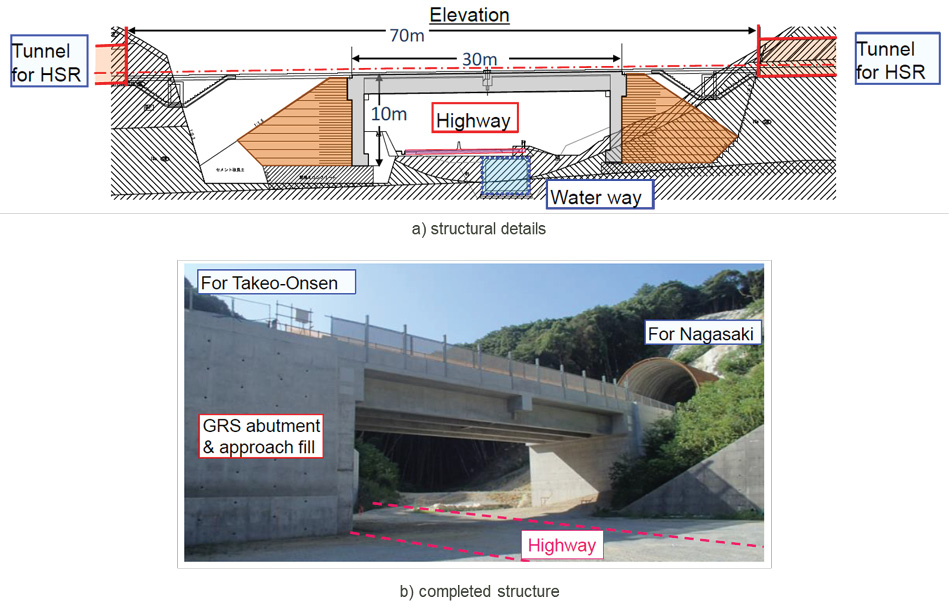
(Shindo and Tatsuoka 2017) reported on the restoration of coastal railway lines in Japan after the Great Honshu earthquake of 2011, which had similar duration and shaking intensity to the Maule earthquake along the coastal areas between Iwaki and Hachinohe. The majority of bridge abutments and embankments were reconstructed using geogrid reinforced soil to provide seismic and wave inundation resistance. The Japanese researchers have developed integral bridges that are connected to the GRS block, significantly increasing bridge deck survivability, refer to Figure 13).
Take Out: Japanese experience provides examples where GRS abutments survived extreme seismic events with full serviceability being maintained. Note: Current Japanese practice in coastal areas is to consider tsunami inundation including potential for over topping.
Figure 13 GRS integral bridge at Genshu for Kyushu Nagasaki Shinkansen route, after (Soga, et al. 2018)
Case History 9 – GRS abutments in the U.S.A.
Transfund (1998) summarises a study into the performance of five GRS structures which were subject to seismic loading during the Loma Prieta Earthquake in 1989. All five structures were undamaged by the earthquake and to date remain in service.
GRS abutment development over the past two decades in the USA focused on large scale testing (shake table results) and insitu monitoring of new built structures. (Helwany, Wu and Meinholz 2012) reported shake table results with input motions of up to 1g, refer to Figure 14. The abutment was found to be fully serviceable after being subjected to 1g of direct shaking, with facing blocks exhibiting minor cosmetic damage.
Take Out: Large scale testing on shaking tables is corroborating numerical analyses, including full 3D FEM and FDM, and field observations (seismic and long duration performance)
Figure 14 Damage after seismic excitation large scale testing, after (Helwany, Wu and Meinholz 2012)

Failures
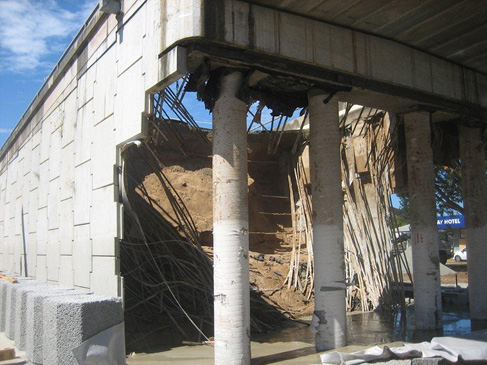
The development of design approaches and construction of GRS abutments were not without issues. Some of the very early structures constructed in Australia and New Zealand have exhibited deformations in excess of the design assumptions.
In New Zealand, one of the early GRS bridge abutments was constructed in the early 2000s in Albany, to the north of Auckland, refer to Figure 15. The bridge structure was supported on piles, (refer Figure 2b). The abutment was made from concrete segmental blocks connected to uniaxial geogrids. Despite best practice at that time indicating that well graded granular soils, i.e. gravels, should be the preferred choice, the abutment was built with cohesive backfill, i.e. clay or silt. Cohesive materials are notoriously difficult to compact and prone to consolidation settlement. There were concerns over the stability of the abutments as the facing deformed after construction, but after a period of one and half years no further deformations were noted, indicating that the backfill achieved equilibrium. The structure continues to support State Highway 1 without any
further distress. In this particular instance the choice of backfill appears to have been inappropriate,
possibly combined with inadequate compaction near the face. Previous case studies clearly indicate the importance of granular backfills that can be appropriately placed and can advantageously interact with the geogrid reinforcement.
Figure 15 Lucas Creek GRS Abutment on SH1 near Albany, showing excessive deformations of the segmental block facing occurring shortly after construction (G Stevens personal library)

In Australia, discussion with practitioners indicated that “..once the patent for reinforced earth walls expired and before RMS [Roads Maritime Services] had a specification for RS walls [R75], several RS walls were constructed in NSW with geosynthetic straps. Unfortunately, on many of these projects (e.g. RS walls on the City West Link and the bridge on Victoria Road over James Ruse Drive) large wall deformations occurred. On James Ruse Drive the deformations were so large the bridge bearings were damaged and the joints on the drainage pipes opened up, so they leaked excessively and the pavement cracked badly. The RS walls on this bridge have been strengthened using soil nails and ground anchors with a concrete facing. It was determined that with our high temperatures and high radiant energy the straps near the facing get very hot and creep excessively. RMS Specification R57 still allows geosynthetic straps but I understand the design provisions for their use are so conservative that they are not really viable”, (Personal correspondence).
The Australian failures may relate to multiple issues. In all reviewed cases the geosynthetics were straps, not geogrids. Polymeric straps were a direct replacement to metallic straps, attempting to introduce polymeric reinforcement to Reinforced Earth type walls. However, straps feature a very different soil interaction compared to geogrids. Straps are mechanically connected to the facing and transfer their loads via friction only into the backfill, whereas, geogrids strengthen the soil by provisioning tensile capacity via increased confinement achieved by dynamic interlock, refer to section 4.3.
Backfill appears to have been a local sand mix with few coarse particles. There are multiple failures of reinforced abutments in Australia related to sand backfill being either not sufficiently compacted or able to be washed out. One notable example is the Tallon Bridge failure. Collapse can be directly attributed to fine grained backfill washing out in flood events and causing a structural collapse of the abutment, refer to Figure 16. Note that the bridge was piled and suffered no ill effects, but the RECO abutment had to be completely rebuilt.
Figure 16 Tallon Bridge failure by backfill washout (G Stevens personal library)
Design deficiencies to account for temperature effects which caused excessive deformations of the facing were also a potential factor. When straps were directly connected to the concrete panel facing, the temperature transferred into the strap and adversely affected the highly tensioned polymeric material. Creep or time dependent viscous-plastic deformations are highly temperature dependent. A small increase in temperature creates a disproportionate increase in creep deformations. Temperature effects should have been considered with the soil-strap reinforcement interaction. Notably geogrids exhibit relatively minor stresses at the facing connections, with principal stresses being distributed well within the soil body. Facing connections are not considered critical for overall stability in geogrid reinforced structures but they are critical for strap reinforcements irrespective of whether metallic or polymeric. Temperature of the soil mass remains constant and records indicates that it is significantly lower than air temperature. Soil mass temperature of an abutment or retaining wall, is not directly affected by the daily temperature changes and remains constant, whereas, straps connected to the facing are likely to have experienced significant daily temperature changes. It is not known what polymers were used in the bridge construction but some polymers are more affected by temperature than others. Whilst geosynthetic reinforcements received criticism, metallic reinforcements are not without issues, notably early onset of severe metallic corrosion from chlorides by environmental exposure or chemical composition of backfill.
In summary, the investigated failures have not been connected to geogrid reinforced abutments and clear design deficiencies were found, such as inappropriate backfill selection. Notably in the New Zealand example, it is questionable whether the choice of reinforcement would have made any difference, with metallic strips likely performing worse that geogrids in clay backfill.
7. Overview of New Zealand studies relevant to GRS abutments
Studies of GRS structures in New Zealand were carried out by Transfund New Zealand in 1998 and 2003 with the findings provided in Transfund Report No’s 123 and 239, respectively, (Murashev 1998) and (Murashev 2003).
The first study conducted a literary review of international design methods and records of measured behaviour of GRS structures under static and seismic conditions with particular focus being placed on projects in USA and Japan (both featuring higher levels of seismicity), (Murashev 1998). The reports reviewed design, construction, and post construction records for GRS structures in New Zealand and compared predicted performance with actual observed behaviour under static and seismic conditions. The study found GRS structures to be cost effective compared to traditionally used retaining structures.
The second study was conducted to prepare guidelines for design and construction of GRS structures in New Zealand, (Murashev 2003) particularly the design of reinforced walls and slopes. These structures are defined as special cases of soils reinforced with geosynthetics, walls being defined as mechanically stabilised earth (MSE) incorporating geosynthetic reinforcement having face inclinations between 60 and 90 degrees from horizontal, and slopes being defined as being similar to walls but with face inclinations less than 60 degrees from horizontal. GRS abutments are not discussed in detail in the guideline.
The current research indicated that there are few recognised and current guidance documents or codes for the use of GRS structures and abutments on Transport Agency’s projects. The information currently being relied upon by the Bridge Manual is considered to no longer be up to date with current technical knowledge.
8. Roadblocks to implementation of GRS Abutments in New Zealand
Version 3 of the Bridge Manual describes MSE [Mechanically Stabilised Earth] systems as “relatively new materials with widely varying properties and a relatively limited history of application and proven performance” . Version 3 of the Bridge Manual was the first version to include an acceptance process for MSE – in response to the rapid development of the technology which occurred during the 1990s and early 2000’s. MSE structures in the context of the Bridge Manual are all reinforced soil structures, with metallic or geosynthetic reinforcements.
In recent years, common application for MSE structures on infrastructure projects in New Zealand have been in reinforced embankments and reinforced slopes. A natural development in the use of this technology is to explore the use of reinforced abutments in New Zealand. The Bridge Manual v3.3 currently does not allow ‘extensible’ reinforcement for use in abutments. Under the Bridge Manual only metallic reinforcements are permitted in bridge abutments directly supporting bridges, (refer to Figure 2c).
Despite the fact that there is a project specific Departure Process under the Bridge Manual that would potentially allow for these structures; this process is not preferred by designers and contracting partners as it presents a risk of noncompliance, creates potential conflict with peer reviewers and can be time consuming to prepare and get approval for.
The fact that GRS abutments are specifically excluded in Waka Kotahi guidance documentation makes them a difficult choice to adopt by designers and peer reviewers, even outside Waka Kotahi’s projects as most councils also rely on the Bridge Manual for council vested roading projects.
The inability to use GRS abutments for Waka Kotahi projects creates pinch points. For starters there is only one product type and supplier in the market; the Reinforced Earth Company (RECO) using metallic (inextensible) reinforcements as defined in the Bridge Manual.
GRS abutments structures, for all intents and purposes do appear to work, and international experience suggests that they technically and economically outperform traditional abutment structures, (Morsy and Zornberg 2017) and (Zheng, et al. 2017). So why are practitioners not designing these structures, and clients not demanding them?
Discussions with designers, Waka Kotahi subject matter experts, suppliers, contractors and academic researchers indicated:
- Lack of knowledge on how GRS abutments work, including reluctance by bridge designers to use ‘novel’ design and construction approaches.
- Specifiers fear that changes to the overall design framework may have unintended consequences, affecting well established designs that have worked for the past decades.
- Geogrids and their in-soil performance are not well understood and are stigmatised by past failures that arguably were not related to them.
- The first generations of geosynthetic reinforcements, mainly made from HDPE with significant amounts of amorphous polymer structures, did exhibit creep at higher stress levels – this was seen as a negative material behaviour, despite operational stress levels being well below any Sherby-Dorn instability levels, as materials were characterised at rupture strain levels rather than actual operational strain levels.
9. Design Frameworks
The following sections review international design approaches for GRS abutments and draw out the key issues that need to be considered in New Zealand. Geotechnical engineering design practice, for the most parts, utilises Limit Equilibrium approach. This approach often conflicts with structural engineering design, where Limit State design is the norm.
With respect to the introduction of geogrid reinforced structures into modern Civil Engineering practice during the 1970’s, the design methods were based on established Limit Equilibrium approaches, (McGown and Ozelton 1973). Many of these early design methods utilised a number of empirical assumptions and large Global Factors of Safety were introduced to ensure that collapse did not occur, (Holtz and Massarsch 1976). Despite this, the design outcomes were still generally more economic than other geotechnical solutions available at that date. As a result, GRS structures were rapidly accepted (Jarret, Lee and Riddell 1977).
In the 1990’s, the Limit State design approach system was developed in geotechnical engineering. This involved fundamental changes in the basic design philosophy from previous Limit Equilibrium approaches. Calculations of deformations or strains within the reinforced soil mass were introduced as an important design criterion, rather than strength of the material. In the beginning of the first decade of the 21st Century, national and international design codes and methods employed in the design of GRS were seeking to implement the Limit State design approach. However, in most cases Partial Factors in combination with Global Factors of Safety were introduced, to ensure that design outcomes were close to those based on the Limit Equilibrium design codes and methods. Thus, the possible improvements and economies to be derived from designs employing the Limit State approach were not being achieved, (McGown 2000) and (Bathurst 2014).
Whilst most countries adopted Limit State principles, many design approaches still utilise earlier design evolutions. Accordingly, great care is needed to adopt design codes in New Zealand on the basis of designs developed in other parts of the world. In contrast, countries like Australia and New Zealand can greatly benefit from research and design development elsewhere and manage their design standards to achieve safe and economic highway structures without replicating efforts made elsewhere.
Advanced seismic design is only practiced by a few countries in the world, especially considering strong and prolonged earthquake shaking (>0.35g for >20sec). Any design approach adopted in New Zealand will need to include provisions of state-of-the-art seismic design.
10. Design considerations
Geotechnical design approaches developed in the past decade in North America and the European Union shifted to full Limit State design to align geotechnical and structural design and achieve satisfactory soil-structure-interaction [SSI]. New Zealand geotechnical practice has readily adopted US and European based design methods, as most European and US geotechnical design guidance documentation is freely available and in English.
The latest and currently considered the most advanced GRS abutment design guidance, was published in 2018 by the US Department of Transport. It details the design for integrated bridge systems and non-integrated bridges, (US Department of Transportation 2018). Limit State design is considered the current best practice with Limit Equilibrium or Hybrid approaches being mothballed (but still very much around). The design of GRS abutments should be undertaken using Limit State principles, especially seismic design. This would align New Zealand design with international best practice. Refer to Figure 17.
Figure 17 Summary of important considerations for GRS abutments
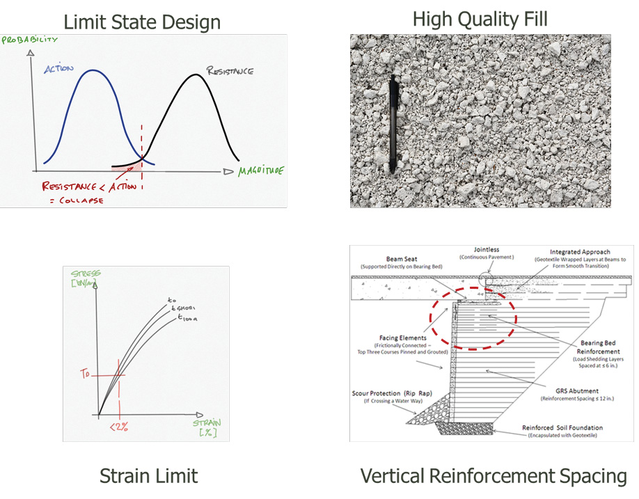
Geogrid materials should have a long-term performance record, but creep elongation for modern materials is of a lesser consideration as the characteristic design strength is determined at low elongations (<2% strain). Structural monitoring of GRS abutments indicated that strains developed under operational conditions are significantly smaller, often 0.2 to 0.5%, than those used to determine the material characteristic strength at rupture with strain levels often exceeding 5%, (Abu-Hejlah, et al. 2000), (Abu-Hejleh, et al. 2002), (Bathurst 2014), (Detert and Thomson 2013), (Herold 2005), (Tatsuoka, Uchimura and Tateyama 1997), (Uchimura, et al. 2004), and (Van Duijnen, et al. 2012). Most modern geogrids show small or negligible creep elongations at operational stress levels.
Soil has to consist of geotechnically competent materials, generally well graded granular angular fill with high crushing resistance, able to be consistently compacted well in excess of 98% of its Maximum Dry Density at or very near its Optimum Moisture Content. Composite behaviour between the geogrid and the backfill is achieved by a combination of reduced spacing, as well as high quality, well-compacted backfill specifications and consideration for facing stiffness.
Vertical spacing of the geogrid layers, especially near the bank seat, are recommended to be about 250 to 300mm and 450mm to 600mm in the main soil body.
Facings are not considered structural elements and are provided as a means of confinement for compaction and to prevent loss of material, and are selected based on project durability, maintenance needs, aesthetics and other requirements. This allows for wrap around construction with false (non-structural) cladding, common in Japan.
Mechanical connection of the geogrid to the facing is not necessary, as the lateral earth pressures at the face of a GRS mass is not significant and a connection failure is not a critical failure mode.
External stability of the GRS abutment must be verified against possible failure modes including sliding, bearing resistance and global stability, especially considering seismic actions. Overturning is not considered a possible failure mode due to the restraint from the bridge superstructure and abutment geometry. Internal stability checks include bearing resistance, deformation, settlement and required reinforcement strength.
11. New Zealand Design Guidance
The current Waka Kotahi design guidance for bridge structures on their roading networks is given in the Bridge Manual. The current version (V3) was issued in 2013 by the New Zealand Transport Agency, setting out the criteria for the design and evaluation of bridges for use on State Highways. Due to lack of other guidance documentation or standard codes of practice in New Zealand, it forms the basis for design for bridge works elsewhere in New Zealand. Version 3 was the first to include an acceptance process for mechanically stabilised soil using geosynthetics. Amendments were subsequently introduced, with Version 3.3 current as of October 2018. Most of the revisions were aimed at seismic design of bridge structural systems.
11.1 Bridge Manual v3.3
The Bridge Manual (BM) contains only three (relatively brief) pages on the specification of material properties and design outcomes relating to GRS abutments.
BM 3.3 Section 6.8.1 sets out requirements for GRS and geosynthetic product approval, (Waka Kotahi Oct 2018). Approval to use geosynthetics in abutments is at the discretion of SMEs (subject matter experts) at Waka Kotahi. An approval process is necessary to provide a framework within which an application can be made in an efficient manner, and which safeguards the Waka Kotahi’s approach to the delivery of quality infrastructure works that equal or exceed global standards. The approval process set out in the Bridge Manual is unique to geosynthetic materials.
Reduction factors applied in the design shall be as the manufacturer / supplier recommends, or a combination of the manufacturer / supplier recommendations and default values recommended by NZTA research report No. 239. Noting that this report No. 239 is at the time of writing almost 20 years out of date, and refers to Limit Equilibrium and Hybrid design approaches. The author notes that all design values derived by this approach should be considered with great care within a Limit State design framework as they may not be appropriate.
BM 3.3 Section 6.8.2 further sets out requirements for GRS material properties and performance, quality control procedures, and design factors. The manual requires the use of integrally connected polymer reinforcement with apertures that permit ‘significant’ mechanical interlock with the surrounding soil or rock. A 100-year design life is required.
BM 3.3 Subsection 6.8.3 sets out requirements for quality assurance and index properties of GRS materials to demonstrate compliance with the values identified in the Transfund New Zealand Research Report No. 239.
Transfund New Zealand Research Report No. 239 (as referenced under BM 3.3. Subsection 6.8.2 of the Bridge Manual) published in 2003 provides guidelines for design of GRS walls and GRS slopes including design examples. Design of GRS walls and slopes considers internal and external stability considerations for static and seismic loading conditions. Pseudo-static stability methods are used to verify internal stability under seismic loading. Although GRS abutments are identified in the report no specific design guidance for GRS abutments is provided.
11.2 Amendments
This study indicated that the following items could be included in a future revision of the Bridge Manual to include GRS abutment design:
- Definition of terms is to be updated to define earth slopes and earth retaining structures, including geosynthetic reinforced slopes and walls. This amendment would bring the Bridge Manual in line with other international codes and guidance documents and sets the scene for geotechnical design. FHWA guidance for example matches geotechnical design with established structural bridge design.
- Clarification of performance criteria, e.g. permissible settlement of an abutment. This amendment would set standards and limits for displacement criteria, including clarification of post construction settlement and settlement at various performance limits, namely SLS [serviceability limit state], DCLS [damage control limit state] and CALS [collapse avoidance limit state]. DCLS and CALS are terms specific to Bridge Manual and could be very loosely interpreted as ULS [ultimate limit state] and MCE [maximum credible event] – both are important seismic performance limits states ensuring service provision on the roading network.
- Changes to Section 6 of the Bridge Manual to permit ‘extensible’ reinforcements used in abutments, subject to satisfactory deformations being maintained. Terms ‘extensible’ and ‘inextensible’ are defined in BM 3.3 Section 6.6.8 and refer to ‘inextensible’ (usually steel) or ‘extensible’ (usually geogrid) reinforcement, and it is considered to be an archaic way to classify materials.
- Updating the Bridge Manual geotechnical reference documentation, listing relevant design documentation for MSE structures in general, and GRS abutments in particular. This section would need to be updated to reflect design guidance using the Limit State approach.
- Definition of load and resistance factors for GRS abutments and MSE structures in general.
- Definition of MSEW (mechanically stabilised earth walls) and RSS (reinforced soil slopes), while independent from GRS abutments, and changes to design framework these structures.
- The above amendments would be aimed to update critical references and allow designers to use GRS abutments within the design framework of the Bridge Manual. However, as GRS abutments are considered a specialist design discipline, steps will need to be taken to ensure satisfactory design outcomes, including the selection of peer reviewers knowledgeable and experienced with GRS abutments and close supervision of the designs by the Waka Kotahi SMEs and industry experts.
11.3 Long term ambitions
Over the longer term, the industry should focus on developing New Zealand specific case studies and capturing experience in construction of these structures by contracting partners of Waka Kotahi. While initially GRS abutments may only be proposed for single span bridges (simple structures), more complex structures are likely to benefit.
A review of Japanese case studies is highly recommended, especially collaboration with Prof Tatsuoka’s group at Tokyo University that lead the seismic design of GRS abutments used on major public infrastructure, including most bullet train bridges in high seismic areas and tsunami inundation zones. At the same time Prof Zornberg’s team at the University of Texas has made important contributions to state-of-the-art design and their input is seen to be critical to implement a full Limit State design and appreciate the soil-structure interaction between the bridge superstructure and the reinforced ground.
GRS abutments could offer significant advantages in the D&C [design & construct] space where cost effective, smart and fast solutions are needed and enable cost and programme savings. It is not unreasonable to assume that ground improvement in combination with GRS abutments could provide significant cost savings over the traditional D&C approach using deep piles for the bridge and ground improvement to support the abutment. To fully leverage on this opportunity more design practitioners need to be familiar with GRS abutments.
The industry will need to respond, with more practitioners needed to be trained to act as designers and peer reviewers. To effectively implement GRS abutments critical thinking is needed and peer reviewers will need to be knowledgeable.
12. Discussions
Research into GRS conducted internationally by NCHRP, and US Department of Transport, and locally by Transfund New Zealand, consistently conclude that GRS abutments represent a safe alternative to conventional concrete retaining wall structures or piled abutments. Where non-performance was noted or failures occurred those were related to design deficiencies such as inappropriate backfill selection. GRS have proven to be more stable than conventional structures, especially subject to extreme loading conditions. GRS abutments can be designed to exhibit either rigid or ductile behaviour under combined sustained, traffic and seismic actions. This allows for fine tuning of bridge supports to match superstructure response; effectively GRS can provide the required stiffness for soil-structure interaction.
From studies conducted in the US and Europe, the reported benefits of GRS abutments include:
- Increased flexibility compared to reinforced concrete or piled abutments.
- High stability and ductility under normal operational actions and extreme actions.
- Reduced potential for abrupt differential settlement to occur at the transition from approach embankments to the bridge abutment.
- Reduced lateral earth pressures on facings which can eliminate the need for a structural facing and allow for non-structural architectural facings to be used.
- Reduced cost, increased construction rate, and reduced requirement for construction plant in comparison to pile supported or ground bearing reinforced concrete abutments.
- GRS abutments in certain instances may remove the requirement for deep pile foundation systems, but ground improvement may be needed.
The studies in the USA, Japan and South America found that GRS abutments perform very satisfactorily under seismic loading due to the following:
- The tensile strength of geosynthetic materials under short term actions such as earthquakes is significantly higher than for static conditions and provides ‘reserve’ capability to draw upon in extreme [overload] events.
- Confinement and dynamic interlock within a soil layer significantly increases the mechanical properties of the soil-geosynthetic composite.
- Ductility of GRS structures is generally not considered by current design methods, however, as they are ‘flexible’ structures they will exhibit ductile behaviour.
- Integral bridge-abutments were pioneered in Japan and were extensively used on the recovery of coastal transport corridors after the March 2011 Earthquake and Tsunami. These systems were designed to be extremely resistant to strong and prolonged seismic shaking and inundation from flood waters, including overtopping.
This study did identify a number of roadblocks affecting geosynthetic MSE structures and GRS abutments in particular. However, changes to the Waka Kotahi Bridge Manual and updating of the relevant supporting guidance documentation to the latest state of knowledge can be considered straight forward as there are international precedents.
13. Conclusions
The findings from the literature review clearly indicated that GRS abutments do work, and they are able to significantly outperform conventional bridge support structures. This applies internationally and there are no apparent reasons why it would not apply on the New Zealand roading and rail networks.
Whilst, the above work focused on Waka Kotahi, who have the responsibility for the State Highway network, it is anticipated that once GRS structures are included in the Bridge Manual, local roading authorities will most likely start to use these structures. Cost conscious clients that do not depend on the Bridge Manual design guidance, including mine operators, already utilise GRS abutments to support their bridges, in some instances to support significant traffic loads from mining operations.
In summary, the overall goal arising from this work is to focus on communication and education of practitioners and contracting partners to ensure that implementation of innovative and new construction methods is executed without excessive design and construction risks, at lower costs than conventional approaches.
14. References
- Abu-Hejlah, N, W Outcalt, T Wang, and J G Zornberg. 2000. Performance of geosynthetic-reinforced walls supporting the Founders/Meadow bridge and approaching roadway structures. Report 1: Design, Materials, Construction, Instrumentation, and Preliminary Results, Colorado Department of Transportation Research Branch.
- Abu-Hejleh, N, J G Zonrberg, T Wang, and J Watcharamonthein. 2002. “Montored displacements of unique geosynthetic-reinforced soil bridge abutments.” Geosynthetics International, January: 71-95.
- Bathurst, R. 2014. “Reinforced soil walls — design and construction.” The Bridge and Structural Engineer, 15-24.
- BE 3/78. 1978. Reinforced earth retaining walls and bridge abutments for embankments. UK, Department of Transport, Memorandum Bridges.
- Bonaparte, R, R R Berg, and J P Giroud. 1985. Soil Reinforcement Design Using Geotextiles and Geogrids. Los Angeles, USA: ASTM Committee D-35, Geotextiles, Geomembranes and Related PRoducts, 69-116.
- Brugger, P J, R DOM Gomes, and M Conte. 2012. “Rebaixamento da Linha Férrea de Maringá Utilizando Muros em Solo Reforçado.” Proceedings of the GIS Brazil CURSOS (In Portuguese).
- Bush, D I. 1988. Evaluation of the effects of construction activities on the physical properties of polymeric soil reinforcing elements. Fukuoka, Japan: Proceedings of the International Geotechnical Symposium on Theory and Practice of Earth Reinforcement, 63-68.
- Da Silva, A EF, P J Brugger, and B Engenharia. 2012. “Análise do Comportamento de Muro de Contenção Portante em Solo Reforçado a partir de Monitoramento de Campo.” Congresso Brasileiro de Mecanica dos Solos e Engenharia Geotechnica (COBRAMSEG).
- Detert, O, and G Thomson. 2013. “Geogrid-Reinforced Bridge Abutments: Report on a Full Scale Test and Executed Projects.” Advances in Geotechnical Infrastructure, 241-246.
- Detert, O, and G Thomson. 2013. Geogrid–Reinforced Bridge Abutments:Report on a Full Scale Test and Executed Projects. Geotechnical Society of Singapore, 241-246.
- Dyer, M R. 1985. Observation of the stress distribution in crushed glass with applications of soil reinforcement. MPhil thesis, Oxford, Uk: University of Oxford.
- Fawzy, E M, and J R Bathurst. 2014. “A new approach to evaluate soil-geosynthetic interaction using a novel pullout test apparatus and transparent granular soil.” Geotextiles and Geomembranes, June: 246-255.
- FHWA. 2015. Synthesis of Geosynthetic REinforced Soil (GRS) Design Topics; Pblication No FHWA-HRT-14-094. US Department of Transportation Federal Highway Administration.
- Helwany, S, J Wu, and P Meinholz. 2012. NCHRP 187: Seismic design of geosynthetic-reinforced soil bridge abutments with modular block facing. web only, National Coopertaive Highway Research Program.
- Herold, A. 2005. “Brückenwiderlager aus KBE-Kunststoffbewehrte Erde, Einsatzgebiete Und Anwendungsgrenzen.” Geotechnik-Kolloquium. Freiberg: Technische Institut für Geotechnik der Universität Bergakademie Freiberg. 195-217.
- Herold, A. 2006. “Brückenwiderlager aus KBE-Kunststoffbewehrte Erde, Einsatzgebiete Und Anwendungsgrenzen.” Sächsisches Textilforschungsinstitut Bautextilien-Symposium, Bautex 2006. Chemnitz: Institut für Technische Textilien GmbH. 1-12.
- Herold, A. 2002. “The first permanent road-bridge abutment in Germany built of geosynthetic-reinforced earth.” Edited by Gourc and Giroud Delmas. Proceedings of the 7th International Conference on Geosynthetics (7ICG). Nice: Balkema.
- Herold, A, Y Aydogmus, and H Sander. 2008. “Large Constructions and Bridge Abutments: Solutions with Geosynthetic-reinforced Earth.” Proceedings of Structures Congress 2008 Crossing Borders. Vancouver. 1-10.
- Holtz, R D, and K R Massarsch. 1976. “Improvement of the stability of an embankment by piling and re-inforced earth.” 6th ECSMFE. Vienna. 473-478.
- Huesker. 2012. Huesker — walls and slopes. Product information, Gescher: Huesker Synthetic GmbH.
- Jarret, P M, R A Lee, and D VB Riddell. 1977. “The use of fabrics in road pavements constructed on peat.” Proceedings of the International Conference on the Use of Frabrics in Geotechnics. Paris. 19-22.
- Kanazawa, Y, K Ikeda, O Murata, M Tateyama, and F Tatsuoka. 1994. “Geosynthetic-reinforced soil retaining walls for reconstructing railway embankment at Amagasaki.” In Recent Case Histories of Permanent Geosynthetic-Reinforced Soil Retaining Wall, edited by Tatsuoka & Leshinsky, 233-242. Rotterdam, The Netherlands: AA Balkema Publishers.
- Kasugai, A, and M Tateyama. 1992. “Application of geosynthetic-reinforced soil for bridge abutments.” In Earth Reinforcement Practice, by Ochiai, Hayashi and Otani, 363-368. Rotterdam: Balkema.
- Kessel van, M T, and H Hangen. 2015. “Possibilities for applying geosynthetics for building new and redeveloping existing bridge abumtnets.” Georesources Journal — Mining, Tunnelling, Geotechnics and Equipment 7-16.
- Koerner, R M. 2012. Designing with Geosynthetics. Vol. 6th edition. Xlibris Corp.
- Kongkitkul, W, T Uchimura, F Tatsuoka, and D Hirakawa. 2004. “Residual deformation due to the viscous property during cyclic loading of geosynthetic reinforcement.” Proceedings of the 3rd Asian Regional Conference on Geosynthetics. Seoul. 988-995.
- Kupec, J. 2000. “Combined sustained and short-term load testing of geosynthetics.” MSc Thesis, University of Strathclyde, Glasgow, UK.
- Kupec, J. 2004. The application of the ISE approach to the deisgn of geosynthetic reinforced soil structures. PhD thesis, Glasgow, UK: University of Strathclyde.
- Kupec, J, and A McGown. 2001. Modelling the behaviour of geosynthetic reinforcements used to resist combined sustained and shock loading. Kyushu, Japan: Proceedings of International Conference on Geosynthetics, 89-94.
- Kupec, J, and A McGown. 2004. “Testing related to the determination of design and long-term be-haviour of polymeric geogrids.” 4th International Conference on Advanced Engineering Design — AED. Glasgow.
- Lo, S R. 2004. “Application of Numerical Modelling to the Design of Reinforced Soil Walls for Infrastructure Projects-Some Australian Experiences.” GeoAsia2004: 3rd Asian Regional Conference on Geosynthetics: Now and Future of Geosynthetics in Civil Engineering. Seoul.
- Loke, K H. 1991. Effects of lateral boundary yielding on large scale unreinforced and reinforced soil walls. PhD thesis, Glasgow, UK: University of Strathclyde.
- McGown, A, and J Kupec. 2001. “Modelling the load-strain-time behaviour of metallic and polymeric reinforcements in soil structures.” Proceedings of the 18th Canadian Congress of Applied Mechanics. St John’s, Newfoundland, CA: Memorial University of Newfoundland. 20-207.
- McGown, A, and M W Ozelton. 1973. “Fabric Membranes in flexible pavement construction over soils of low bearing strength.” Civil Engineering and Public Works, January: 3-7.
- McGown, A, K C Yeo, I Yogarajah, and K Z Andrawes. 1990. T4/4 Identification of a dynamic interlock mechanism. Performance of reinforced soil structures, London: British Geotechnical Society, 377pp.
- Mid-America Earthquake Centre. 2010. The Maule (Chile) Earthquake of February 27, 2010. Case Study, MAE Centre.
- Morsy, A M, and J G Zornberg. 2017. “A tale of two bridges: Comparison between the seismic performance of flexible and rigid abutments.” GeoAfrica 2017. Marrakesh: MaIGS. 1000-1008.
- Murashev, A K. 1998. Design & construction of geosynthetic-reinforced soil structures in NZ: review & discussion paper. Wellington: Transfund No. 123.
- Murashev, A K. 2003. Guidelines for design & construction of geosynthetic-reinforced soil structures in New Zealand. Wellington: Transfund No.239.
- NCHRP Report 556. 2006. Design and Construction Guidelines for Geosynthetic-Reinforced Soil Bridge Abutments with a Flexible Facing. Design Guidance, National Cooperative Highway Research Program, Washington D.C., USA: Transport Research Board.
- Peng, X. 2017. Evaluation of load transfer mechanisms between soil and geogrid using tranparent soil. PhD thesis, Austin, USA: University of Texas.
- Rajapakse, Ruwan. 2016. Geotechnical Engineering Calculations and Rules of Thumb. Butterworth-Heinemann.
- Schmoltczyk, U, and K Hilmer. 1982. Baugrundverbesserung. 3. Vol. Sonderdruck: Grundbautaschenbuch. 2 vols. Verlag Wilhelm Ernst & Sohn.
- Shindo, Y, and F Tatsuoka. 2017. “Restoration of Sanriku Railway by utilizing reinforced soil structures to enhance earthquake and tsunami resistance.” Journal of JSCE, 10-26.
- Smoltczyk, U. 1996. Grundbautaschenbuch. 5. Vol. 2. Verlag Wilhelm Ernst & Sohn.
- Soga, D, Y Takano, T Yonezawa, H Koda, M Tatsyma, and F Tatsuoka. 2018. “Design and construction of various type GRS structures for a new high-speed railway.” Proceedings of the 11th International Conference on Geosynthetics. Seoul.
- State New York Dep of Transportation. 2015. Geotechnical Engineering Manual: Guidelines for design and construction of geosynthetic reinforced soil integrated bridge abutments. GEM-28, rev #1, New York: Geotechnical Engineering Bureau.
- 2020. Structure, Components and Parts. August 27. http://www.historyofbridges.com/facts-about-bridges/bridge-parts/.
- Tateyama, M, O Murata, K Watanabe, and F Tatsuoka. 1994. “Geosynthetic reinforced retaining walls for bullet train yard in Nagoya.” In Recent Case Histories of Permanent Geosynthetic-Reinforced Soil Retaining Wall, edited by Tatsuoka & Leshinsky, 141-150. Rotterdam, The Netherlands: AA Balkema Publishers.
- Tatsuoka, F, J Koseki, and J Kuwano. 2014. “Natural disaster mitigation by using construction methods with geosynthetics (earthquakes).” 10th International Conference on Geosynthetics. Berlin.
- Tatsuoka, F, T Uchimura, and M Tateyama. 1997. “Preloaded and prestresed reinforced soil.” Soil and Foundations 37 (3): 79-94.
- Tatsuoka, F, T Uchimura, M Tateyama, and J Koseki. 1997. “Geosynthetic-reinforced soil retaining walls as important permanent structures.” In Mechanically Stabilised Backfill, edited by Wu, 3-24. Rotterdam, The Netherlands: AA Balkema Publishers.
- Uchimura, T, F Tatsuoka, T Hirakawa, and T Shibata. 2004. “Effect of reinforcement stiffness on deformation of reinforced soil structures under sustained and cyclic loading.” Proceedings of the 3rd Asian Regional Conference in Geosynthethics. Seoul, South Korea. 233-239.
- US Department of Transportation. 2018. Design and Construction Guidelines for Geosynthetic Reinforced Soil Abutments and Integrated Bridge Systems. FHWA-HRT-17-080, Georgetown: Federal Highway Administration.
- Van Duijnen, P G, T Linthof, C AJM Brok, and S JM Eekelen. 2012. “Measuring deformations of a 10 m high geosynthetic-reinforced earth retaining wall.” Proceedings of the 5th European Geosynthetics Congress. Valencia: Proceedings Vol 5. Topic: Soil Improvement and Reinforcement. 157-161.
- Waka Kotahi. Oct 2018. Bridge manual, third edition SP/M/022. NZ Transport Agency.
- Wilson, J C, and B S Tan. 1990. “Bridge Abutments: Formulation of Simple Model for Earthquake Response Analysis.” Journal of Engineering Mechanics 1828.
- Won, G W, T Hull, and L De Ambrosis. 1996. “Performance of a geosynthetic segmental block wall structure to support bridge abutments.” In Earth Reinforcement Vol.1, by H Ochiai, N Yasufuku and K Omine, 543-548. Rotterdam: Balkema.
- Wood, J H. 2015. “Earthquake Design of Bridges With Integral Abutments.” 6th International Conference on Earthquake Geotechnical Engineering. Christchurch: ICEGE.
- Zheng, Y, AC Sander, W Rong, PJ Fox, PB Shing, and JS McCartney. 2017. “Shaking table test of a half-scale geosynthetic-reinforced soil bridge abutment.” Geotechnical Testing Journal.
- Zornberg, J G, B Christopher, D Leshchinsky, J Han, B Tanyu, F T Gebremariam, P Shen, and Y Jiang. 2018. Definition of the boundary conditions for composite behaviour of geoysynthetic-reinforced soil structures. National Cooperative Highway Research Program Transportation Research Board, The National Academies of Sciences, Engineering, and Materials.