Why use surface geophysical methods in geotechnical investigations?
An opinion of a geophysicist
1 Introduction
Over the last two decades geophysical methods have become increasingly popular for many applications in modern engineering practices, especially in the disciplines of geotechnical and earthquake engineering. ‘Making the invisible visible’ is more and more where engineering standards, codes of practices, and professionals are heading to. We now live in an era where sites need characterising, where having a realistic 3D model of a site is often regarded superior to scattered 1D information, and where a decreasing number of clients and their insurances are willing to accept risks originating from unknown or insufficiently known ground conditions. This is where the use of surface geophysical methods (i.e. where geophysical signals are recorded from sensors placed on the surface) provides the geo-professionals with a few major advantages; they are non-invasive, cover large areas in relatively short times, and generate continuous 2D and 3D data sets of the underground physical properties. All of which contribute to gaining a better overall understanding of the ground that is developed on.
While it is one goal of this article to highlight the advantages of applying surface geophysical methods to geotechnical engineering questions, it is also an attempt at clearing some of the experienced misconceptions that seem to exist between the disciplines. For the geophysical methods to unfold their full potential it is necessary that their advantages and limitations are well communicated and understood. Early geophysical contractor involvement helps with this and is crucial to ensure the geophysical data is collected in a way suitable to address the tasks appropriately. While there is knowledge about certain geophysical methods in the engineering community, when it comes to geophysics, there is often no ‘one size fits all’ approach possible and many different factors determine whether an investigation will be successful or not.
The following sections will give a brief overview of some of the ‘most wanted’ geophysical outputs and demonstrate, with two different examples, the usefulness of integrating a surface geophysical investigation into a geotechnical program early on.
2 Shear wave velocity and surface geophysical methods typically used in engineering applications
The increasingly created need through modern regulations to assess the seismic hazard at a site, have contributed to the increased use of the seismic methods in the engineering industry. One physical ground parameter that is of particular interest to geotechnical and earthquake engineers is the shear wave velocity (Vs). The NEHRP Site Classification, Eurocode 8 and NZS1170.5:2004, to name only a few building standards, all require the use of the shear wave velocity over the first 30 m of the underground (i.e. Vs30) to classify a site. NZS1170.5:2004 ranks the surface geophysical methods of obtaining Vs30 second in a list of seven options. Only the use of invasive geophysical methods that do not require the velocity to be obtained by inversion of the geophysical measurements (i.e. a mathematical process of matching the geophysical data to a ground model) are considered a better choice. However, the latter methods are invasive and only point specific.
There are a few surface geophysical methods available to measure shear wave velocity, the most prominent of them probably is the Multichannel Analysis of Surface Waves (MASW). MASW is often used to produce 2D images along straight profile lines. It is important to understand though that the test is a 1D measurement that produces a shear wave velocity versus depth profile at the midpoint of the total active geophone array. The 2D sections are then obtained by interpolating between several closely spaced MASW tests along a profile line. While there are standards for measuring Vs in situ with invasive geophysical methods or in the laboratory, no standard exists to date that is setting out how to measure this property by means of using surface geophysical methods. This leaves the geotechnical professional with little control over the geophysical data quality. Some guidelines (e.g. NZ Ground Investigation Specification, 2017) set out a framework for what shall be included in a surface geophysical report. However, these guidelines completely ignore any aspects of good data acquisition or processing practices. Two very crucial steps to generate a meaningful data set. Choosing to work with a qualified and experienced geophysicist is therefore highly important. A good source of information for experts and non-experts alike is the guideline for surface wave analysis (Foti et al., 2017) developed by an international panel of expert users.
Another seismic method often used in engineering applications is seismic refraction. This recovers the P-wave velocity (Vp) profile of the ground by extracting the refracted P-wave information of a seismogram (i.e. first signal arrivals). Several different ways of analysing this data exist, with the more sophisticated technique of seismic refraction tomography (SRT) being able to recover a detailed 2D Vp model of the underground. The model data can be used directly as P-wave velocity in engineering calculations, as a priori information in MASW processing, or can be interpreted in terms of geological units. An ASTM standard is available for seismic refraction testing (ASTM D5777-00).
Probably one of the most used non-seismic surface geophysical method (together with Ground Penetrating Radar (GPR) which is not discussed here) is the electrical resistivity tomography (ERT). While of less interest from an earthquake or liquefaction point of view, the method is a lot more economic to apply (as compared to seismic) and produces 2D profiles or even 3D volumes of underground resistivity distribution in a relatively short time. This information can be used to extrapolate seismic testing to other areas of a site and is often translated to geological interpretations. The measured electrical resistivity as a physical ground property is also used in earthing design calculations. ASTM D6431-18 provides a standard for this method.
3 Examples of integrating surface-based geophysics in geotechnical investigations
For larger scale projects, and especially when budgets for ground investigations are tight and only allow for limited geotechnical testing, surface geophysical investigations can make a tremendous difference in the volume of acquired knowledge about the ground. However, often the scope for geophysics is unclear and regarded as a simple add-on to the invasive testing program. This then becomes quickly too expensive and is discarded all together. In contrast, if a geophysical scope is integrated as part of the geotechnical program and used as a tool to connect fewer dots and fill in the data gaps in a smart way, budgets can be satisfied while gaining a more comprehensive image of the ground. Two different examples are used to illustrate this principle. Both examples are taken from real projects, though, due to respecting client confidentiality no specific details can be given.
Example 1: Seismic resilience and geological stratigraphy
Owners (and their insurers) of infrastructure, structures and buildings with high importance levels (e.g. IL3+) increasingly consider undertaking seismic resilience assessments for their assets to enable them to manage the risks and protect the structures by improving the ground, where necessary and possible, before a potential disaster occurs. In this example, an approximate area of 30 hectares needed to be assessed by the geotechnical engineers. Existing boreholes and CPT data were available in certain areas of the site and needed to be complemented by a new site investigation filling in the information gaps. The site is located on reclaimed land spanning several decades of reclamation stages.
The strategy of the geotechnical lead was to use surface geophysical testing (MASW) not only as a means of obtaining in situ shear wave velocity information, which was then used to determine the site class across the area, but also as a reconnaissance tool for positioning the new invasive borehole and CPT testing. This approach has the advantage that areas of concern can specifically be targeted with the more expensive (by volume of information gained) invasive tests rather than randomly positioning these within the boundary of the site.
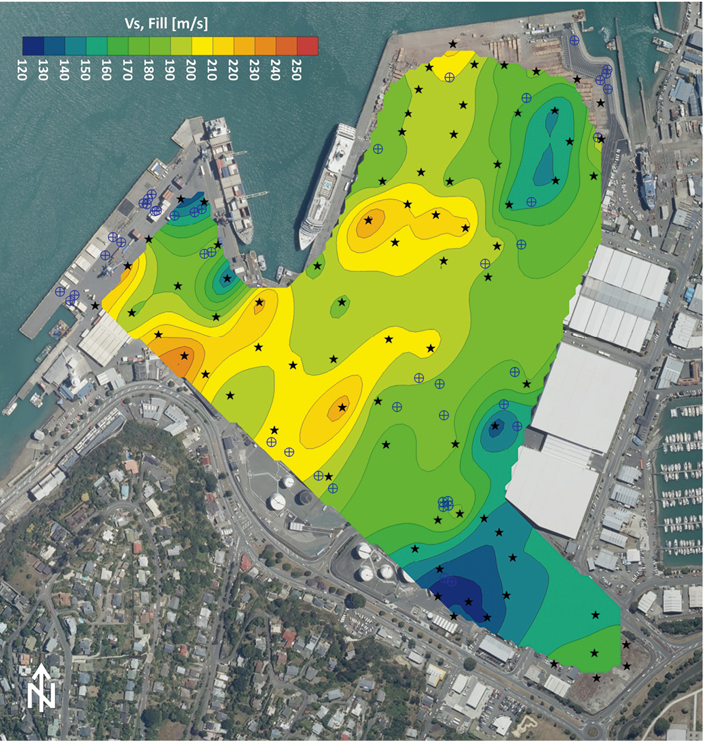
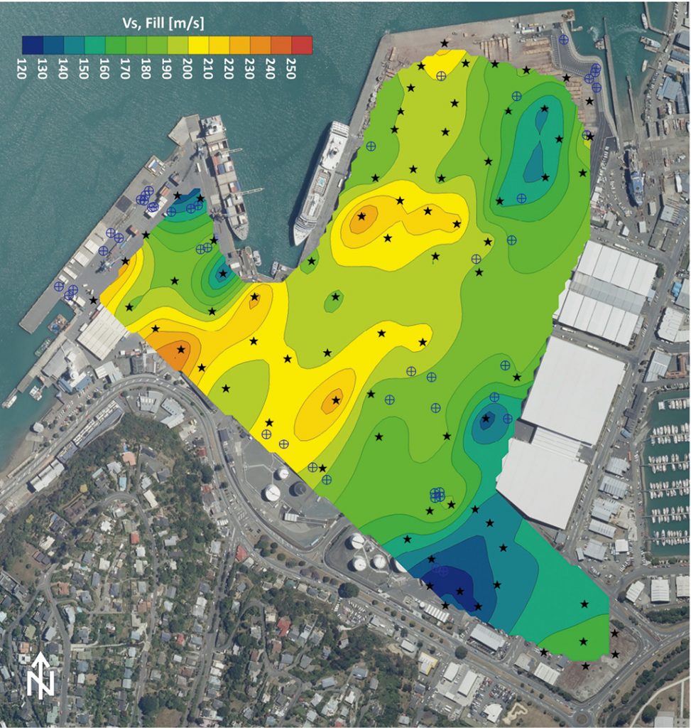
For covering large, laterally inhomogeneous areas, a few 2D profiles may not give a complete image of geological variations, especially in a situation where land was reclaimed over several stages and with different fill material. Therefore, the MASW testing was spread out across the site to cover a larger part and provide a pseudo-3D understanding of lateral Vs and geological stratigraphy changes across it. Figure 1 shows an example of an interpolated contour map depicting the average shear wave velocity of the reclamation fill (first ~4-5 m bgl). Areas of potentially softer or denser material are easily identifiable this way.
Figure 1: Contour map of the average shear wave velocity (Vs) of the reclamation fill produced from 79 MASW Vs measurements (black stars mark the test locations) using Kriging interpolation. Invasive CPT and borehole data were available at the locations marked by blue crossed circles (i.e. pre-existing data).
The MASW shear wave velocity models were also interpreted for geological units with the aid of the already existing invasive data. Then the identified layer boundary depths were used to produce contour maps similar to the one shown in Figure 1. Although, the geophysical data were not collected along specific profile lines, using these interpolated maps of depth to specific geological boundaries also allowed to draw cross-sections (see Figure 2) which provided a better understanding of vertical and lateral boundary changes in the vertical plane view. Furthermore, seismic refraction data (Vp) collected along with the MASW data provided an estimate of the depth to groundwater. This information and existing invasive data were used during the inversion of the MASW models to combat some of the non-uniqueness of the inversion procedure and hence making the models more robust.
Figure 2: Two example cross-sections drawn from the MASW models and interpolated depths to geological layers. Different colours mark different geological units. The boundary to white below the deepest layer marks the maximum depth of the MASW data. Existing CPT logs were superimposed where the cross-sections crossed these or were located close by. Cross-sections were drawn through areas with a higher density of MASW data available to make them less dependent on interpolation.
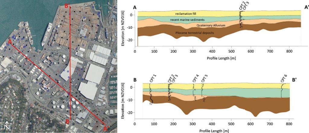
Close collaboration between the geophysicist and the geotechnical engineer ensured that the geophysical data set was used to its full potential. As is indicated in Figure 2, the investigation depth achieved with the surface based MASW method did not everywhere provide the attempted 30 m below ground level (averaged around 20-25 m bgl) due to site and source restrictions. The geotechnical engineer then obtained Vs30 by extending the MASW Vs models to 30 m using the Boore et al. (2011) correlation.
New borehole, CPT, and seismic CPT (sCPTu) test locations were decided on after release of the geophysical draft report. The latter were used to compare to the MASW obtained shear wave velocities. These matched greatly and gave further confidence in the comprehensive data set. One of the main advantages of the surface-based geophysical method was that the achieved depths were significantly larger as compared to sCPTu. This was due to the CPT refusing as shallow as 4 m bgl (max. depth reached at the site was 17 m). In addition, MASW data was collected in areas where the CPT or borehole drill rigs were not permitted. The flexibility to operate in a large variety of terrain and environments is a very useful characteristic of the surface geophysical methods in general.
Example 2: Feasibility & resource consent investigation for large-scale development
When medium to large size developments are in the feasibility or consenting stage, often a site-wide understanding of the site conditions, geology and groundwater level is needed. Obtaining a thorough image of the underground and being able to characterize a site early on can help to plan for unsuitable or problematic ground conditions, price a project correctly (e.g. earthworks costs), and avoid under- or over-designing the planned structures. In this example, obtaining a reliable indication of the depth to basalt was crucial for the client to determine if developing the desired site was feasible due to large excavation volumes needed in some of the areas. As a secondary task the geophysical information was used to assist with site classification and the identification of the distribution of clays, silts, and sands. Invasive and non-invasive tests were arranged in a grid-like way to get a relatively dense coverage of the 60-hectare site.
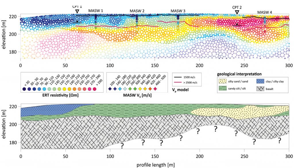
Because the seismic methods are generally the more expensive of the geophysical tests, the bulk of the geophysical investigation was done using ERT. This allowed to cover a lot of ground with real 2D profiles in a relatively shorter time. The information was used to distinguish between clayey, silty, and sandy soils as well as identifying the boundary to basalt. The SRT method was then used to get a separate model of the groundwater depth (Vp ~ 1500 m/s) and the depth to basalt (here, Vp > 2500 m/s), and to constrain the ERT model interpretation along several profile sections across the site. At each of the SRT profile locations, MASW data were collected in addition. The Vs information further helped constraining the ERT and SRT model interpretations and provided a secondary indication of the liquefaction potential across the site (in addition to CPT).
In Figure 3 an example of a 300 m section of one of the geophysical profiles is given. The background colours of the top image are representing the ERT model (i.e. resistivity). The SRT Vp models are superimposed with black and pink lines for interpreted groundwater and basalt boundaries, respectively. MASW models are imaged with coloured cross-dots (vertical lines). CPT and borehole information were superimposed on the geophysical models where available. All information was then used to ‘translate’ the geophysical models to geological units as shown in the example bottom section in Figure 3. ERT helped to understand the large-scale geology with depths of up to 40 m bgl obtained. The seismic methods were focused on shallower depths of around 10-20 m bgl.
Figure 3: The top image shows the geophysical models of ERT (background colours), SRT (black and pink lines), and MASW (coloured cross dots). Where CPT (and borehole) data were available, these were superimposed on the geophysical data for aiding the interpretation of ground material types. Using all available information across the site geological models were drawn as shown in the bottom image.
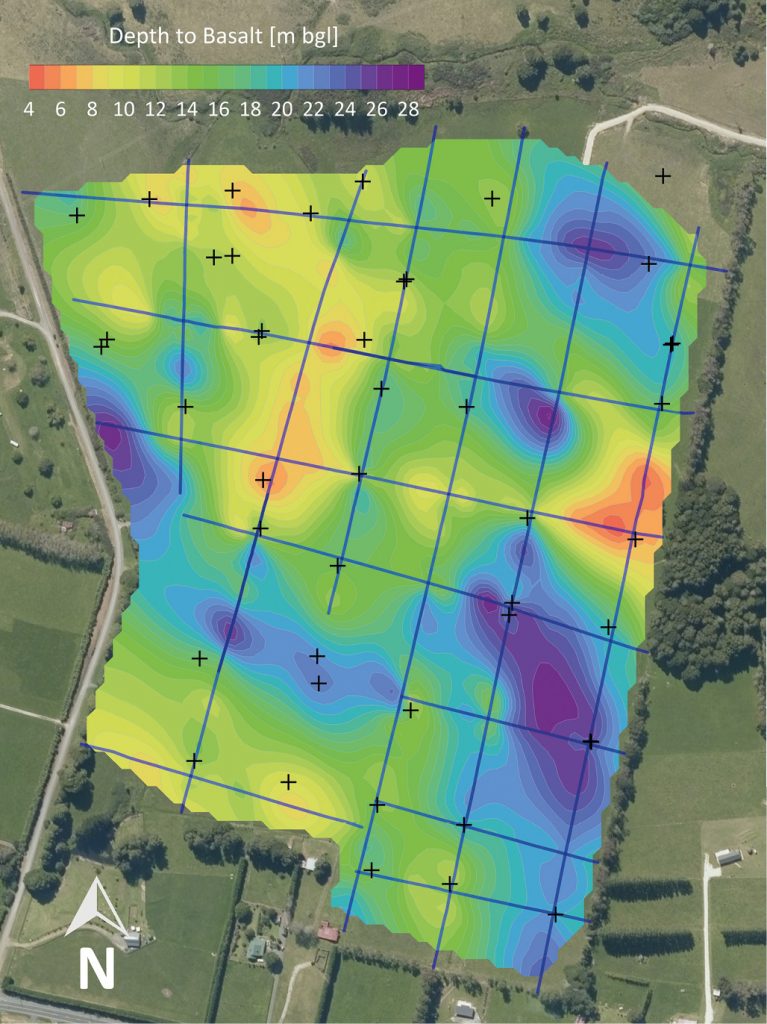
To have all this information was extremely valuable because the ground turned out to be highly variable not only in the vertical, but especially in the lateral dimensions. This was evident from the invasive testing (boreholes and CPT’s) and confirmed by the continuous geophysical data that connected these points (e.g. between CPT 1 and CPT 2 in Figure 3). Using the borehole information and the interpreted boundaries to basalt (and groundwater) along the geophysical profile lines, contoured maps of the depth to basalt (see Figure 4 for an example) were produced to give a quick overview of this information to the geotechnical and civil engineers. They were then able to overlay this information with the planned cut and fill contours in CAD to establish whether the excavations were likely to intersect basalt.
At this site using one geophysical method alone would not have been sufficient to discern between some of the ground materials (e.g. high resistive sand/gravel and weathered basalt in ERT), which highlights that depending on the task, or several tasks, of a geophysical investigation, more than one geophysical method may be necessary or beneficial. A geophysicist can design the required geophysical program according to targets and budgets and ideally should be consulted by the geotechnical engineers before finalisation of the geotechnical investigation program.
Figure 4: Interpreted depth to basalt across one part of the site. Interpretation was made base on geophysical and invasive data available and is interpolated in areas where no data was available. Geophysical data were collected along the blue lines. The longest profiles measured 700 m (for scale). Black crosses mark the locations of CPT and borehole testing.
4 Concluding remarks
With an expanding global population, the need arises more and more to develop land that may not be optimal for infrastructure to be built on (e.g. on swamps, near fault lines, on liquefiable soils, on or close by instable slopes, etc.). It will become increasingly important to ensure the risks associated with the underground architecture is well known and can be addressed in the design. The advantages of using surface geophysical methods as part of a geotechnical investigation for such assessments are versatile as demonstrated by the two examples presented in this article. In summary, these are:
Non-invasiveness and little restrictions regarding accessibility in difficult terrain (e.g. steep slopes, dense vegetation, areas where invasive testing is not possible/allowed).
Depth coverage vs. associated cost (i.e. there is no correlation between cost and obtained depth, hence a profile to 40 m depth may cost the same as a profile to 10 m depth).
Time spent vs. data volume obtained (e.g. a 200 m 2D ERT profile to 30 m depth may take around 4 h to collect and analyse, whereas a series of boreholes to cover the same volumes would take considerably longer (apart from possibly being completely unfeasible)).
Power to identify vertical and lateral geological variations at the same time (i.e. 2D & 3D capabilities).
It is also important to highlight that there are, as with everything in life, some limitations to the surface geophysical methods. These are mainly related to the indirect nature of obtaining the ground models (i.e. the non-unique character of the inversion procedure) and mean that surface geophysical information may have a lower resolution than invasive methods. This is especially true for data obtained at larger depths, an increasing distance away from the geophysical signal source. However, if used by experienced professionals and regarded as a tool to optimize a geotechnical program, the advantages of using these methods outweigh the limitations by far. After all, only greater data volumes will generate a higher information density which in turn provides a better understanding of a site.
References
ASTM Standard D5777-00, 2000: Standard Guide for Using the Seismic Refraction Method for Subsurface Investigation. ASTM International, West Conshohocken, PA, 2000
ASTM Standard D6431-18, 2018: Standard Guide for Using the Direct Current Resistivity Method for Subsurface Site Characterisation. ASTM International, West Conshohocken, PA, 2018
Auckland Council (and collaborators), 2017: New Zealand Ground Investigation Specification. Volume 1: Master Specification. Auckland Council, New Zealand.
Boore D., Thompson E., and Cadet H., 2011: Regional Correlations of VS30 and Velocities Averaged Over Depths Less Than and Greater Than 30 Meters. The Bulletin of the Seismological Society of America. 101. 3046-3059. 10.1785/0120110071.
CEN 2004: European Standard EN 1998-1: 2004 Eurocode 8: Design of structures for earthquake resistance. Part 1: General rules, Seismic action and rules for buildings. European Committee for Standardization, Brussels, Belgium.
Foti, S., Hollender F., Garofalo F., Albarello D., Asten M., Bard P.-Y., Comina C., Cornou C., Cox B., Di Giulio G., Forbriger T., Hayashi K., Lunedei E., Martin A., Mercerat D., Ohrnberger M., Poggi V., Renalier F., Sicilia D., and Socco V., 2018: Guidelines for the good practice of surface wave analysis: a product of the InterPACIFIC project. Bulletin of Earthquake Engineering, 16:2367-2420
Building Seismic Safety Council, 2003: NEHRP Recommended Provisions for Seismic Regulations for New Buildings and Other Structures (FEMA450). 2003 Edition. National Institute of Building Sciences, Washington, D.C., USA.
New Zealand Standard NZS1170.5:2004, 2016: Structural design actions. Part 5: Earthquake actions – New Zealand (Incorporating Amendment No. 1). Standards New Zealand – Paerewa Aotearoa, Wellington, New Zealand.