
Case study: Seismic foundation design for the new Wellington Children’s Hospital
Abstract
The much-anticipated Wellington Children’s Hospital is currently under construction and scheduled to open in 2021. The project was made possible by a generous $50m donation from 2017 Wellingtonian of the Year Mark Dunajtschik.
At the discretion of the benefactor and the Capital and Coast District Health Board (CCDHB) it was decided that the structure would be designed to an Importance Level 4 (IL4) for a 50-year design life. As part of this work a site-specific hazard assessment was completed by GNS which resulted in peak horizontal ground accelerations of 0.7g and 1.4g for the SLS2 and ULS design cases.
The building will be four-storeys with approximate dimensions of 34m by 68m with a height of 18.4m above founding level. The structure consists of concrete filled square columns supported by Friction Pendulum Bearings (FPB) on a 700mm thick concrete raft.
The ground beneath the building footprint is an infilled gully, with depth to rock varying from 3m to 15m below founding level, with the upper 6m comprising highly variable contaminated fill, underlain by liquefaction-prone alluvial deposits.
The geotechnical aspect of the assessment was to mitigate excessive differential settlement (to allow continued FPB performance). Complex numerical modelling identified that the estimated deformation of a shallow-founded raft would be beyond acceptable tolerances and this resulted in a driven timber pile solution being adopted.
Due to the high seismic demands, the capacity of the timber piles to cope with the inertial and kinematic loads was considered critical to the seismic performance of the building.
This paper presents a case study of how the complex simultaneous inertial and kinematic effects on the piles were modelled and suggests that the simplified logical procedure adopted would be a practical approach for similar projects with base-isolation technology.
Keywords: Foundation Period, Resonance, Spectral Response, Inertial, Kinematic.
Introduction
The much-anticipated Wellington Children’s Hospital is currently under construction and scheduled to open in 2021. The proposed hospital is a four-storey building with approximate plan dimensions of 34m by 68m. The total height of the structure is 18.4m above foundation level (including the plant room). The period of the structure was calculated as 0.94sec in the longitudinal direction and 0.90sec in the transverse direction. This paper summarises the site investigation and assessment for the detailed pile design.
Initially Coffey was requested to do a detailed assessment of a raft / base slab only foundation. A non-linear time history analysis was performed and excessive differential settlements during the SLS2 earthquake case were identified which exceeded the allowable displacement. This resulted in a pile solution being adopted.
Large bored piles were being designed as the preferred option, but during the detailed design stage, the environmental and health and safety impacts of the design became apparent as the infill material is contaminated and proceeding with bored piles would require use of full protective suits, wash stations, etc. Coffey was engaged to investigate a range of alternative options with the following restrictions:
- Minimise spoil/waste
- No / low vibrations
Given the above, a driven timber pile solution was adopted.
Site Investigation
The investigations involved 7 boreholes, 37 CPTs, Refraction Microtremor (ReMi) Surveys (utilises ambient vibrations and noise signals – picked up by linear array of geophones) and downhole shear wave velocity measurements. The spread of CPT tests across the site provided detailed information on the variability in soil layering across the site and the bedrock profile. From the investigations the following generalised ground model was developed:
Table 1: Summary of Ground Profiles
| Unit | Description | SPT N | Density/
Consistency |
Min and Max Depth Range (mbgl) |
| FILL | Silty, Sandy Gravel and detritus material (Contaminated) | 4 – 7 | Loose | 0.0-5.0 |
| Alluvium | Gravels, Silts, Sands | 10 – 20 | Medium Dense | 4.5-15.5 |
| Rock | Highly to slightly weathered Sandstone/ Siltstone | 24-50+ | Very Weak to Strong | 2.6-15.5+ |
Several phases of groundwater monitoring were completed, with a standing water level of 4.5m below the underside of raft being established. A design groundwater level of 4.0m was used.
Driven Timber Pile Trial
A trial involving six 8m long driven timber piles was completed using both vibration and drop hammer methods. Noise and vibration monitoring were completed, and acceptable levels were recorded.
Insitu Lateral Load tests
Insitu lateral load tests were carried out onsite – one static pushover test was undertaken, followed by two cyclic loading lateral load tests. The measured P-y behaviour was used to calibrate the piling computational model which was set up using the Coffey in-house software package “Combined Load Analysis of Piles” (CLAP, Version 6.2, Rev T9, July 2013) which is based on elastic continuum theory. The CLAP model was set up with an unfactored static ground model, and with a free head condition.
For a horizontal load of 62 kN, CLAP initially under-estimated the level of displacement both for the push-over test and for the cyclic tests. Given that the load tests mostly applied load onto the Fill, the stiffness of the Fill was reduced to make the P-y behaviour predicted in CLAP match the onsite tests. It was found that for both the push-over and cyclic tests, a reduced static stiffness of Ev = 14 MPa (and Eh =10 MPa) predicted displacements which were inside the performance envelopes of both the push-over and cyclic tests at 62 kN load. Based on this iterative calibration process, a reduced Fill stiffness of Ev = 14 MPa was adopted for the remainder of the CLAP models to be undertaken.
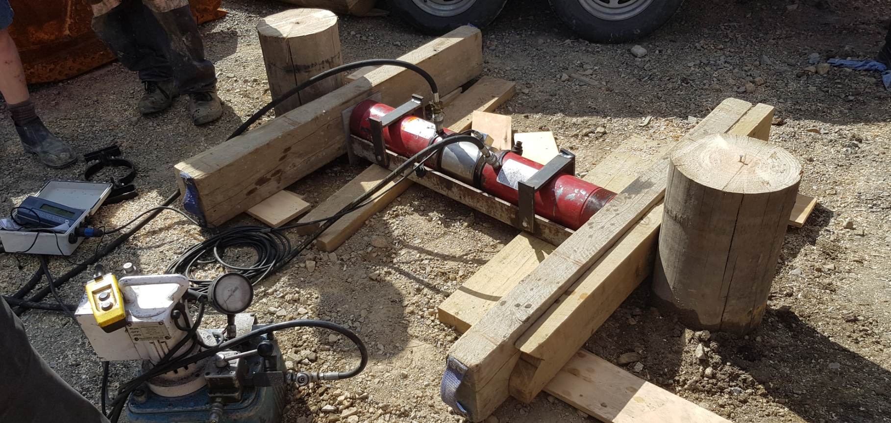
Figure 1: Lateral pile testing
Design Criteria
Structural Criteria
- The following design criteria was provided by the Structural Engineer for the assessment of the ground/raft foundation performance:
|
|
|
|
|
|
|
|
|
|
|
|
Site Seismic Response
A site-specific seismic study was completed by GNS and a total of 10 accelerograms were provided (Houtte and McVerry 2018) for use in the seismic assessment. Linear scaling factors, k1, were also provided to convert the accelerograms to a 10% (SLS2) and 2% (ULS) probability of exceedance in 50-years. Of specific interest was the inclusion of several subduction interface events, such as the 9.0 Mw Japan earthquake of 2011.
As part of the detailed assessment, ground motion parameters were assessed using Cubrinovski and McManus (2016) and compared with the GNS recommended values. These are presented below in Table 3.
Table 3: Ground Motion Parameters
| Design Case | Importance Level | % NBS | Design Life | Annual Probabilty1 | C0,1000 | Meff2 | Ru or Rs | f | PGA (GNS Report) |
| SLS1 | 4 | 100 % | 50 | 1/25 | 0.44 | 6.2 | 0.25 | 1.33 | 0.11 |
| KE3 | – | – | – | – | – | 7.8 | – | – | 0.2 |
| SLS2 | 4 | 100% | 50 | 1/500 | 0.44 | 7.1 (8.0) | 1.0 | 1.33 | 0.45 (0.7) |
| ULS | 4 | 100 % | 50 | 1/2500 | 0.44 | 7.1 (8.0) | 1.8 | 1.33 | 0.81 (1.4) |
1 – Table 3.3 (Structural Design Actions, NZS1170 Part 5: Earthquake Actions 2004)
2 – Table 6A.1 (NZTA 2016)
3 – KE = Kaikoura Earthquake – PGA taken from nearby strong motion records
As can be seen above, the site-specific assessment from GNS substantially increased the seismic design demand. We understand this is due in part at least to the introduction of larger subduction events in the hazard model.
Geotechnical Assessment of Soils Subjected to Earthquakes
Lateral displacements due to cyclic loading
A check on peak cyclic lateral displacement was been undertaken following the Tokimatsu and Asaka 1998 methodology. This method estimates cyclic displacements from estimates of cyclic shear strain based on (N1)60cs values, which we converted from CPT testing (a better sample set was established from the CPT’s due to the number of test locations completed relative to the few boreholes and traditional SPT N tests). The CPTs were clustered together based on common profiles and location and a typical CPT profiles were developed. The results showed cyclic lateral displacements in the order of 110mm-130mm in the centre of the site through the gully and 45mm-75mm at the edges of the site through shallow soils.
Liquefaction Assessment
A detailed assessment using proprietary software was completed using the Boulanger and Idriss (2014) method for liquefaction triggering. A back analysis of the November 2016 Kaikoura Earthquake (KE) was completed to establish appropriate values for Plastic Limit (PL) (0.66) and Corrected Fines Content (Cfc) (0.0).
The results of the analysis are summarised in Table 4 below. Note the CPT depths range from 2.7m (no liquefaction and shallow rock) to 15.1m in the middle of the gully with significant liquefaction.
Table 4: Liquefaction Values – Index Assessment – Full Profile
|
|
|
|
|
|
|
|
|
|
|
|
Note: Bracketed numbers represent average ± standard deviation
The above calculated free field settlements and LPIs indicate the site could experience anything from insignificant to high effects from liquefaction. This is due to the highly varied profile across the site.
Foundation Design
Design Philosophy and Process
The overall design philosophy was defined as follows:
The timber piles are to provide continued vertical support to the underside of the raft, to ensure the acceptable tolerable settlement is achieved during the SLS2 and ULS design cases. The timber piles will be spaced in a close grid formation and are not connected to the raft (pinned top and bottom – see figure 2 below) but are held together as a group by the non-liquefiable crust creating a ‘piled system’. It is expected that the raft structure would remain elastic during the SLS2 case as the timber piles would mitigate all but a small (<15mm) amount of differential settlement at adjacent column locations. During the ULS design case it is expected that some/majority of the timber piles will experience excessive loading and plastic deformation, however the ductile nature of timber piles and the close spacing/shear number of timber piles will continue to provide a reinforced soil mass, to sufficiently reduce settlement. The raft would be expected to experience some cracking/yielding. The timber piles alone are not expected to mitigate all settlement during the ULS case and the ‘piled system’ is expected to even out settlements to an acceptable level. The stiffness of the soil-pile system is greatly improved over the existing soil profile. This increase in stiffness has resulted in reducing the period of the foundation system and leading to the reduction of cyclic displacement of the earthquake.
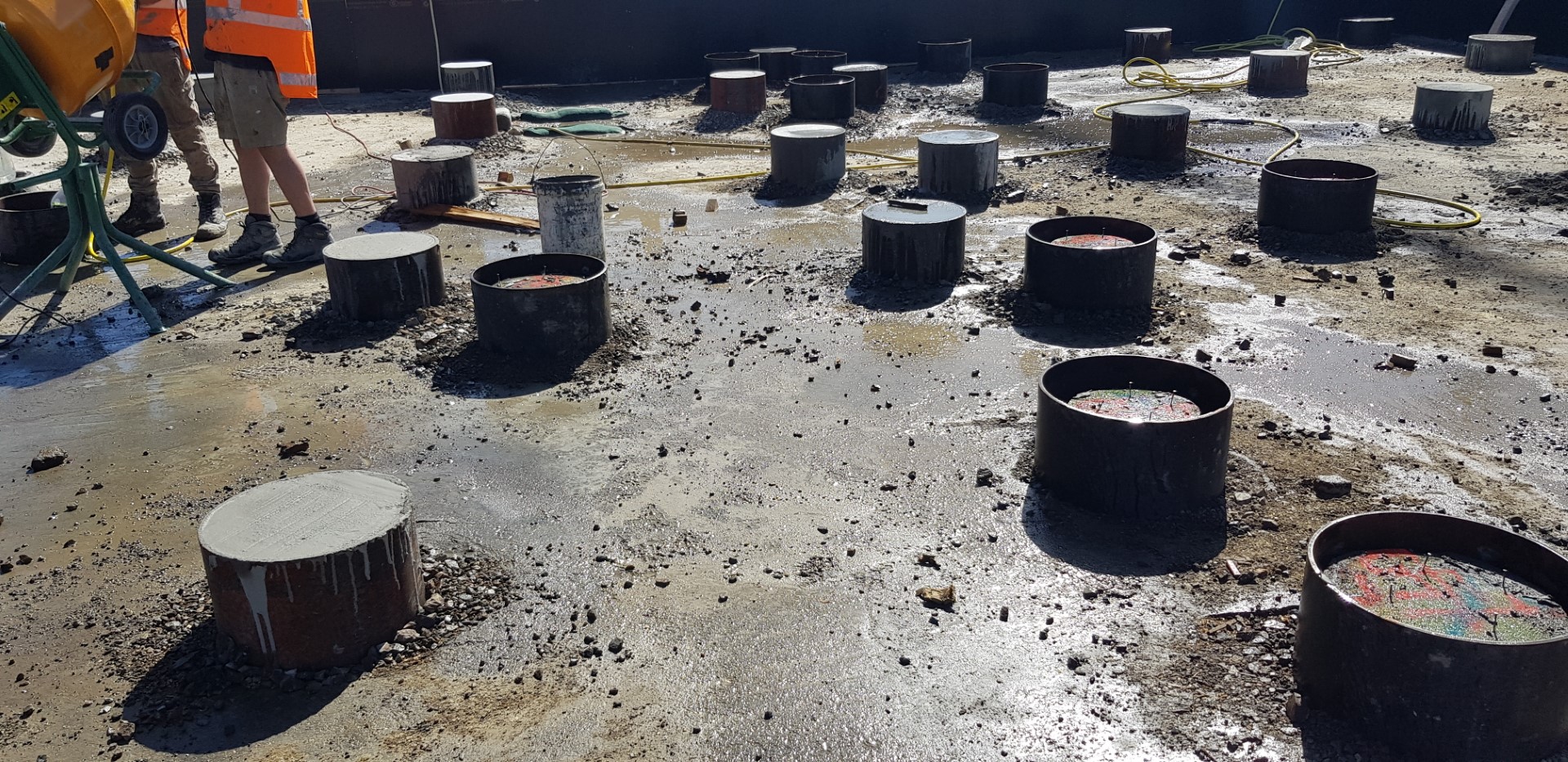
Figure 2: Pile caps undergoing grouting. Site level raised to top of pile caps with hardfill.
The design process involved assessing the axial capacity, structural capacity, inertial effects, kinematic effects and pile group effects. To clarify; inertial loads are earthquake-induced lateral pile head loads applied by the raft/slab and kinematic loads are earthquake-induced lateral ground movements acting along the length of the pile. The combination of inertial and kinematic earthquake effects is a complex phenomenon and the pile performance under these combined loads was a major factor to the pile design overall.
It should also be noted that the base shear demand from the super structure was extremely low (due to the large Friction Pendulum Bearings), with the concrete raft producing most of the base shear.
Ground model sections and material properties
Piles were assessed from both the edge (short piles) and the centre of the gully (long piles) assuming the geotechnical parameters presented in Table 5 below.
Table 5: Material properties for pile design
| Layer/ Unit | ϒ’ (kN/m3) | c’ (kPa) | Φ’ (°) | Static Case (G/G0 = 0.3) Ev (MPa) | Seismic Case (G/G0 = 0.7) Ev (MPa) |
| Fill | 16 | 0 | 34 | 14 | 33 |
| Alluvium | 21 | 0 | 34 | 100 | See comments below |
| Weathered Rock | 22 | 15 | 37 | 150 | 350 |
The horizontal stiffness (Eh) was taken as approximately 70% of the vertical stiffness (Ev). The stiffness values for the Fill were later calibrated based on the insitu lateral load tests, which are discussed above.
A design groundwater was taken to be at 4.0mbgl and so in an earthquake case liquefaction was assumed to be from that depth to the top of the Weathered Rockhead. The liquefiable alluvial zone was modelled as a “virtual layer” (i.e. minimal stiffness values input [E = 0.001 MPa]) in the computational models along the pile lengths.
Timber properties and capacities
Material properties for the timber piles was taken from Timber Structures Standard, NZS 3603:1993. The limiting lateral capacities on individual 250SED timber poles were calculated to be:
- Shear capacity = 109 kN
- Bending moment capacity = 33 kN.m
Base Shear – Sliding Check
Base shear (sliding) was a key consideration during design and a detailed assessment was completed. A summary of the sliding assessment was that during SLS2 approximately 60% of the sliding resistance between the raft and pile will be utilised while during the ULS event the sliding demand exceeds sliding resistance by approximately 10%.
Structural loads and pile spacing
Based on the provided structural loads for the raft and superstructure, a calculated total 836 timber piles (250SED) are required to provide bearing resistance below the raft. The piles were generally spaced 2m c/c, but 1m c/c spacing was also adopted in more heavily loaded areas. The horizontal inertial loads acting on an individual pile head were calculated for SLS2 and ULS with a sliding friction ratio of 1.0.
Strength reduction factors
Strength reduction factors (both geotechnical and structural) were derived for assessing the timber pile performance. The geotechnical strength reduction factor (Φg) was applied to the SLS2 case only, whereas the structural strength reduction factor (Φs) was applied for both the SLS2 and ULS cases.
For both vertical and lateral loads, a geotechnical strength reduction factor (Φg) of 0.7 was derived using the risk-based methodology set out in Section 4.3 of the Australian Piling Standard (AS2159-2009) and a structural strength reduction factor (Φs) of 0.8 was adopted for the timber specimens.
Axial Compression Capacity
The unfactored static geotechnical base resistance of a single pile was calculated to be 6.7 MPa at the rockhead. The skin friction resistance was found to be near-negligible when compared to the end-bearing resistance.
The predicted geotechnical axial capacity was then evaluated and calibrated against the driven pile tests. Using the Hiley Formula for the given installation conditions (i.e. a hammer weight of 820 kg, hammer free-fall height of 1.5m, hammer efficiency of 90%, and a typical penetration of 2mm per hammer blow), the equivalent ultimate pile base resistance was assessed to be 6.6 MPa, which is close to that calculated above. Our calculations also demonstrated that the timber piles satisfy the compressive structural capacity.
Soil Displacement (Kinematic Effects)
To account for the kinematic effects on the pile, the displaced soil profile predicted from the Tokimatsu and Asaka (1998) assessment was then input into the L-pile (Ensoft) piling program to generate the resulting pile actions. The L-pile model assumed free head conditions to allow the maximum pile displacements.
We considered that the base-isolation system between the raft and the superstructure would decouple the foundation (i.e. raft + piles) from the superstructure, and therefore the overall foundation system would be in-phase with the earthquake ground motion whilst the superstructure building would not be in phase. Following this logic, we considered it reasonable to assume that the kinematic forces acting across the piles would also tend to be in-phase with the inertial forces (generated by the heavy raft sliding over the pile head).
Pile group effects
To account for the pile group effects, a 3×3 group pile model was set up in CLAP to compare the performance of the pile group to that of a single pile. The horizontal and vertical loads were applied at the centre of the 9-pile group and were the summation of the loads on each pile head. As the timber piles are not rigidly connected to the concrete raft, the pile heads were input into the model as having a ‘pinned’ connection which is free to rotate.
The group assessment showed that due to the pile spacing and diameter, minimal group effects would occur.
Pile Performance Results
The summary of the pile analysis under SLS2 and ULS conditions is presented below in Table 6. The SLS2 condition was for an inertial load of 50 kN and applied geotechnical reduction factor and liquefaction. The ULS condition was for an inertial load of 72 kN and no geotechnical reduction factors and liquefaction.
These results are for the combined effects of inertial loading and kinematic loading acting simultaneously on a pile as it is in-phase with the ground motion.
Table 6: Summary of Pile Analysis combined kinematic and inertial loading
| Case | Scenario | Max. Actions in the Piles | Pile Displacements | |||
| Axial Force (kN) | Shear Force (kN) | Bending Moment (kN.m) | Lateral Displacements (mm) | Vertical Settlement (mm) | ||
| SLS2 | Long – Single Pile | 160 | 50 | 19 | 122 | ~3 |
| ULS | Long – Single Pile | 160 | 72 | 25 | 126 | ~3 |
Our assessment was that a 250SED timber pile can tolerate the actions in the above table.
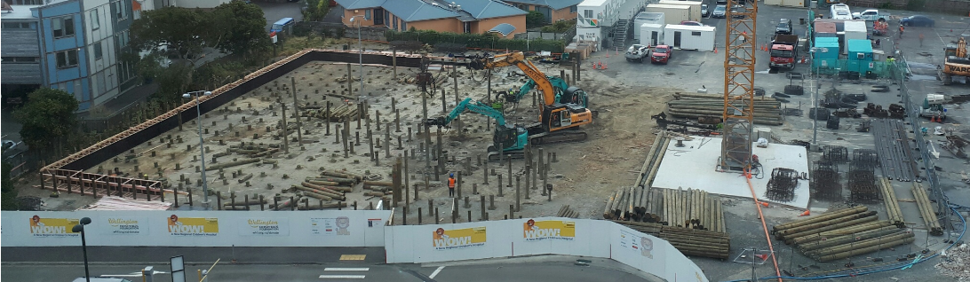
Figure 2: Timber pile installation
Conclusions & Acknowledgements
This paper presents a case study of the seismic foundation design undertaken for the Wellington Children’s Hospital. A key area of complexity was how to simultaneously model the effect of both inertial and kinematic effects on the piles. The procedure we adopted involved modelling the effects of inertial and kinematic effects separately and then superimposing the pile actions and displacements by assuming them to be in-phase, while assuming that the base-isolation system would have decoupled the raft and the superstructure. We consider that this approach is simple, logical and overall conservative. We consider it to be a practical approach for similar structures with base-isolation technology being adopted.
The authors would like to acknowledge the contributions of their colleagues on this project, namely Kah-Weng Ho and Chris Dutil.
References
Boulanger, R, and I Idriss, 2014, CPT and SPT Based Liquefaction Triggering Procedures. UCD/CGM-14/01. Department of Civil & Environmental Engineering, College of Engineering University of California at Davis.
Cubrinovski, Misko, and Kevin McManus, 2016, Earthquake Geotechnical Engineering Practice – Module 1: Overview of the Guidelines. NZGS.
Houtte, C Van, and G McVerry, 2018, Wellington Children’s Hospital Phase 1b: Hazard Disaggregation and Record Selection. GNS.
NZTA, 2016, Bridge Manual (SP/M/022) – Edition 3. NZTA.
Piling- Design and Installation, 2009, AS2159. Standards Australian.
Structural Design Actions, NZS1170 Part 5: Earthquake Actions, 2004, Incorporating Amendment No.1. NZS1170, 5. Standards New Zealand.
Tokimatsu, and Asaka, 1998, Effects of Liquefaction-Induced Ground Displacement on Pile Performance in the 1995 Hyogoken-Nambu Earthquake.
Zhang, G, P Robertson, and R Brachman, 2002, Estimating Liquefaction-Induced Ground Settlements from CPT for Level Ground. Canadian Geotechnical Journal 39: 1168–1180.