ABSTRACT
Trees in urban environments cool cities, capture carbon, and reduce stormwater runoff through enhanced initial losses. However, their root systems require uncompacted soil to grow, a requirement that is inconsistent with optimal pavement performance. To accommodate trees in roadways, carparks and pedestrian accessways, Citygreen Urban Landscape Solutions (Citygreen) have developed recycled plastic modular “geocellular” ground support elements installed beneath, within and alongside pavements to promote root development. The system includes tree pit openings and a skeleton structure of the modular support elements filled with loose soil into which roots can grow. Global use of these modular systems is growing in line with mainstreaming of Water Sensitive Urban Design (WSUD).
Pavement engineers when encountering these products commonly over-engineer the surrounding and overlying pavement to account for uncertainty in the soil-module behaviour. This has reduced the cost competitiveness of the system.
Citygreen and Golder have carried out laboratory testing, numerical modelling and field testing to demonstrate a design process for the soil-module system where placed with relatively shallow cover under trafficked pavements. This will help to reduce perceived risk during the design process, thereby optimising design and reducing cost.
INTRODUCTION
Water Sensitive Urban Design (WSUD) is a key design component of many civil engineering projects and emphasis on the need for WSUD will increase in response to climatic changes. The use of modular geocellular drainage systems is part of WSUD, allowing rainwater harvesting and onsite detention in areas that would otherwise require traditional “pits and pipes” for management of stormwater. An advancement on geocellular drainage systems allows incorporation of loosely placed growing media within a recycled plastic skeleton structure. The purpose of such a system is three-fold; allowing retention and reuse of stormwater, and promoting healthy trees as root growth can be encouraged within the loosely placed growing media. However, there are geotechnical engineering implications when using these systems in urban areas which rely on conventional subgrade and pavement compaction.
Strata™ module systems (Figure 1), developed by Citygreen are examples of geocellular ground support elements designed to be placed beneath and alongside pavements. The typical configuration under pavements includes loosely-backfilled stacked modules wrapped in combigrid, supported on a compacted subgrade or aggregate drainage layer, and confined by a compacted perimeter annulus (Figure 2).


Figure 1: StrataVault™ and StrataCell™ modules
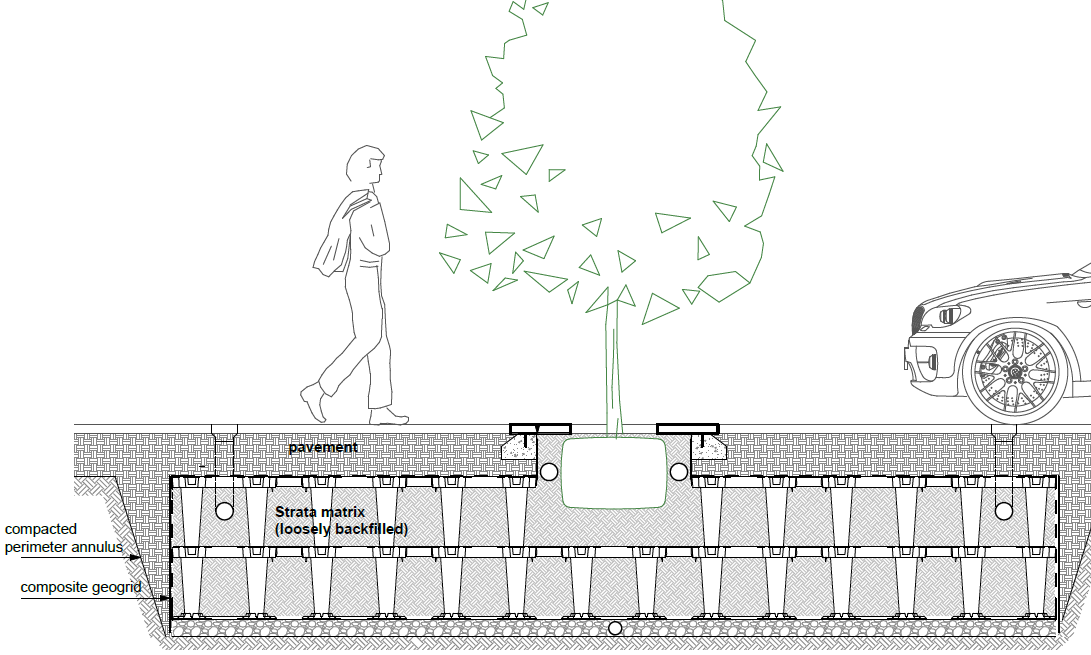
Figure 2: Typical Strata module configuration under pavements
Typical placements of the modules include under pedestrian accessways, carparks, and within roadways. An example of a similar system includes the Silva Cell by DeepRoot Green Infrastructure. Other systems and buried modules have different strength and performance characteristics and the results presented herein cannot be applied to different systems.
Key geotechnical design considerations for modules placed under pavements include:
- Vertical load distribution through any overlying pavement system to the top of the modules
- Load response and vertical and horizontal compressive strength of the modules
- Creep rupture strength of the modules
- Resilient modulus and deformation of the backfilled module system under live loading and/or cyclic loading
- Vertical load distribution through the system to the underlying subgrade
- The potential for strains to develop at the interface between the module matrix and the natural ground or adjacent pavement subgrade
- Construction quality control and construction verification expectations. Citygreen reports that system performance issues have typically arisen from incorrect installation methods, not as a result of module failure
The overall system behaviour is dependent on the installation geometry including stack height, which varies between projects.
CIRIA C737 (O’Brien, et al, July 2016) provides guidelines and recommendations for the design of geocellular systems, for the most part focusing on their use in stormwater attenuation. For placement under pavements, the guide provides recommended serviceability, ultimate and dynamic load factors and recommends careful analysis where cover under pavements is less than 1 m or where minimal differential settlement can be tolerated. The importance of module creep rupture strength over short-term compressive strength is emphasised.
To reduce uncertainty in the behaviour of the Strata™ soil-module system and to help limit overconservative or conversely under-design, Citygreen and Golder have carried out laboratory testing, numerical modelling and field testing to demonstrate a design process and validate performance of the system (with appropriate construction methods) where placed with relatively shallow cover under trafficked pavements.
Vehicular Loading on Buried Modules
Part of the design requires understanding the magnitude of vertical stress imposed by vehicles onto a buried module system. In all cases considered herein, the pavement cover is less than 0.5 m. Long term sustained loading was not considered due to the relatively thin pavement cover.
Elastic stress distribution analyses were carried out using the commercially available software CIRCLY. The analyses considered both serviceability and ultimate loading using wheel loading for different operating regions over the world, as follows:
- Australian Equivalent Standard Axle and AS5100 W80 bridge design loading
- European Eurocode En1990 wheel loading
- USA/Canadian AASHTO H20 vehicle
- 10 tonne truck
- 5 tonne truck
Serviceability analyses were carried out using unfactored wheel loading and ultimate analyses carried out using combined dynamic and ultimate loading factors of 1.2 and 1.8 respectively (note CIRIA C737 now recommends a dynamic factor of 1.25).
Three different pavement types overlying the buried module system were considered in the CIRCLY analysis, with similar subgrade conditions, including:
- Full depth granular pavement
- Asphaltic pavement over unbound granular
- Concrete pavement over unbound granular
Outcomes from the CIRCLY analysis comprised load distribution with depth charts for serviceability and ultimate loading, for each of the above pavement types. Each chart shows vertical stress with depth due to applied wheel loading. The charts aim to allow:
- A designer to understand the minimum cover required over buried modules under ultimate wheel loading in different operating regions, to ensure that modules are not locally overstressed under wheel loads
- Calculation of working stress at the top of the buried modules for further calculation of bearing pressure under the feet of the lowest layer of modules
LOAD RESPONSE OF INDIVIDUAL AND STACKED MODULES
The buried module systems have varying dimensions and geometry as shown indicatively below (Figure 3). Typically, modules are arranged under pavements in rows stacked up to four high, giving typical maximum buried depths of less than 2 m. Top grates are installed across StrataVault™ modules to provide a flat surface for pavement installation.

750 mm
804 mm
Figure 3: Indicative module geometry and dimensions
Individual Module Load Testing
To test the peak ultimate compressive strength of the different module types and strength grades, a series of laboratory crush tests were carried out at the University of Newcastle in New South Wales, Australia. Testing was carried out on modules stacked up to two high with testing also carried out after 10 000 cycles of loading.
The testing demonstrated the rated static strength of the modules was achieved, with and without cyclic loading.
Module Matrix Load Testing
Laboratory Trial
In order to understand load distribution with depth through a module matrix, large-scale laboratory testing was undertaken at the Golder research and development facility at the Port of Melbourne, Victoria Australia.
A variety of different module configurations were tested, with modules stacked between one to four high. A laboratory configuration is shown in Figure 4 below.

Figure 4: Large-scale testing at Golder research and development facility, Port of Melbourne
Empty module assemblies were set up on a concrete floor within a load frame. Concrete pavers were placed over the top row of modules and under the feet, to provide light vertical confinement and a flush surface for testing. Seven load measurement cells (LC1 to LC7 with data loggers) were strategically placed under the feet of the bottom row of modules. A steel plate was used for load application at three different positions (P1 to P3). Two dial gauges were connected to a reference beam and positioned over the steel plate for measurement of deflection. Vertical load was applied using a hydraulic jack.
The vertical load applied to the matrix assembly was intended to simulate typical highway truck wheel loading. In addition, modules were subjected to peak compressive loads up to 2 000 kg and the load held for three cycles of five-minute duration. The positions of load application and load cell placement under the modules are shown in Figure 5 below.

Figure 5: Position of load application and load cell placement (StrataVault™ shown)
Significant outcomes and of the laboratory trial were:
- Stress distribution with depth through the matrix was found to be minimal but improved slightly with increasing stack height
- Geometry of individual modules (shape and number of legs) has greatest impact on peak subgrade foot pressure
- Peak subgrade stress (foot pressure) was observed at the outside corners of the matrix (i.e. Position 3 as indicated in Figure 5 above)
- Measured vertical displacement at peak vertical load during testing of the StrataVault™ modules was up to about 15 mm. Displacement during testing of the StrataCell™ was less than 5 mm
- A relationship was developed between peak subgrade stress beneath the modules and load applied to the top of the module matrix (commonly the underside of pavement level), for various stack heights and module types. Further development of this relationship is required to incorporate the results of field trials
Recognised limitations of the laboratory trial include:
- The absence of soil backfill within and surrounding the matrix may have reduced the ability of the assembly to transfer load laterally with depth
- Placement of the modules on a rigid concrete floor may have reduced the ability for the stacked module system to spread load laterally and would reflect load spread in high strength subgrade conditions
- Displacements were measured at the point of load application only rather than across the top of the whole assembly
- Horizontal displacements were not considered
- Long term creep testing was not carried out (loading was meant to reflect transient traffic loading only)
To further investigate performance of module matrices, an instrumented field trial was carried out.
Field Trial – Lynwood Avenue, Western Australia
The instrumented field trial and testing programme was undertaken to further understand vertical and lateral load distribution through a backfilled module matrix and to better understand the likely vertical stress applied to subgrade beneath the feet of the lowest layer of modules. The testing also allowed field measurement of stiffness behaviour of the module matrix under traffic loading.
With guidance from Golder, the City of Canning installed modules beneath a trafficked pavement at three locations along Lynwood Avenue, Canning, Western Australia. Modules were stacked between two to three rows high. The pavement profile above the modules comprised 400 mm to 460 mm thickness of bitumen stabilised limestone with 40 mm asphalt wearing course (pavement materials were specified by the City of Canning). Recycled crushed concrete was used as the perimeter annulus material between the matrix and the surrounding adjacent native sand subgrade. The design native subgrade California Bearing Ratio (CBR) was known to be 10%.
During installation, two load cells (with data loggers) were placed under the lowest module feet at each of the three trial locations (for a total of six load cells installed). The load cells were positioned with the aim to capture the location of peak loading at module feet as assessed from the outcomes of the laboratory trial, and at a central position where load distribution may occur. Field trial load cell locations are shown in Figure 6.

Figure 6: Load cell placement for field trial (StrataCell™ shown)
Following pavement construction, Falling Weight Deflectometer (FWD) testing was carried out across the pavement (and repeated in successive years). The FWD testing targeted six key locations including over native subgrade, over the modules and over the perimeter annulus. This variety in testing locations allows for comparison of the stiffness response for varying subgrade conditions. During FWD testing, data logging results from the load cells were obtained.
The FWD test results indicated deflection at top of pavement up to about 1 mm with construction over native subgrade, and up to 2.5 mm with construction over a backfilled module matrix. The data was used to:
- Estimate effective CBR of a backfilled module matrix using published relationships
- Understand if load spread through backfilled modules differs from the laboratory scenario where the modules were empty
- Understand if load spread through backfilled modules differs when foundation conditions comprise sand with a subgrade stiffness of CBR 10% rather than a concrete floor
The back-analysed results indicate that the CBR values calculated for the native subgrade generally correlate well with the design subgrade CBR of 10%. Effective subgrade CBR values for the perimeter annulus were variable; and the effective subgrade CBR values for the backfilled modules indicate lower-bound values of 1% to 2%.
Interrogation of the data obtained from the load cells indicated increased lateral load spread and reduced footing bearing pressure measured in the field compared to laboratory conditions.
Design bearing pressure beneath module feet
Incorporating the results of the elastic stress distribution analysis, the laboratory trial and field trial, it is possible to estimate the likely stress at the base of the Strata™ module system for a given traffic loading. The design approach includes the following steps:
- Calculate the working stress at the top of the buried module system using the charts developed from the elastic stress distribution analysis (CIRCLY analysis), for the corresponding pavement type, thickness and vehicle loading
- Use the stress distribution relationships developed from the laboratory and field trials to convert the pressure applied to the top of the system to the pressure applied to the feet of the modules, for the corresponding module type and stack height. These relationships consider the plan area of each module type and its smaller contact area with the foundation soil
Using this design approach, appropriate foundation preparation can be designed to maintain safety margins against bearing failure beneath module feet, for the prevailing native subgrade conditions.
CONSTRUCTION CONSIDERATIONS AND DESIGN DETAILING
Assessment of Interface Strains – Backfilled Annulus Area
Finite element analysis was carried out to assess potential strains at the interface between a typical Strata™ module profile and an adjacent pavement subgrade or natural ground under standard truck axle loading. If not carefully considered, subgrade strain could develop at this interface as a result of the lower stiffness of the modules, resulting in reduced pavement life. To minimise strains, careful consideration of the design stiffness of the perimeter annulus is required.
Design & Construction Considerations
The analyses, laboratory and field testing carried out provide valuable information with respect to design of the buried module system. The following construction stage problems have been encountered, which can be addressed with modification to construction equipment and expectations during proof rolling:
- Pavements built over backfilled geocellular systems must be designed for potentially lower subgrade support than may be provided by the surrounding native subgrade
- Compaction of the perimeter annulus surrounding the backfilled geocellular system is important where pavements transition from native subgrade to the backfilled geocellular system
- Careful consideration of compaction equipment is required when constructing a pavement over a geocellular systems constructed on top of a strong subgrade or on top of an existing concrete slabs. High energy compaction may damage the modules
- Construction quality control should ensure that composite geogrids are properly overlapped and wrapped around the system to maintain integrity
- Very high local stress can occur beneath individual feel of the base layer of modules when designed for higher truck loading, when considering ultimate loading. The effect is more pronounced with StrataVault™ modules compared to StrataCell™ modules due to the geometry of each module and number of legs. Subgrade bearing capacity must be checked. Further development of the load transfer relationship through the modules is required – incorporating the results of field trials – for more accurate assessment of subgrade stress
- Proof rolling during construction must take into consideration the higher deflection response of backfilled geocellular systems in comparison to some native subgrades, particularly when the system is installed within a weathered rock soil profile
- Deflection of the top grate may be higher than deflection of the modules and very thin pavement may not effectively arch over a weaker top grate. In some cases additional geogrid layers may be required to improve load distribution through thin pavement layers
- If present, the aggregate subbase drainage layer should be connected to stormwater for positive drainage to prevent subgrade softening. This is particularly important if rainwater harvesting to the Strata™ system is undertaken as part of WSUD
- Long term creep strength and deflections must be considered where sustained loads are applied to the system
Designers should ensure sufficient hold points are shown on drawings so that quality control during construction is of a high standard. Citygreen indicate incorrect module installation as the main cause of system performance issues observed to date.
Quality control throughout the manufacturing supply chain is also critical. Module crush testing at the manufacturing point is required to ensure compliance with advertised load ratings, and resin batches are traced through the supply chain to project delivery.
Conclusions
The above paper outlines how buried geocellular systems can be designed to support short duration vehicle traffic under road pavements in urban environments, allowing for increased root development and healthier trees. With the increasing emphasis on WSUD, the use of these products will increase, requiring a greater understanding of the geotechnical behaviour of the soil-module systems.
Understanding how geocellular systems spread load vertically and laterally is important in design, and the geometric structure of the systems has a significant impact on the way load is distributed. Not all geocellular systems will behave in the same way.
The use of geocellular systems beneath traffic road pavements have implications on pavement design. Field and laboratory trials have demonstrated that the systems can be effective but are less stiff than most road subgrade conditions.
Numerical analyses, laboratory and field trials carried out by Golder on commercially available Citygreen Strata™ modules provide evidence to support geotechnical design of such systems worldwide.
Careful attention to detail is required during construction with the need for additional construction hold points, different approaches to compaction and proof rolling and, in some cases, site specific earthworks specification documents will improve successful performance post construction.
REFERENCES
Austroads, 2017. Guide to Pavement Technology Part 2: Pavement Structural Design
Austroads, 2009. Guide to Pavement Technology Part 4G: Geotextiles and Geogrids
British Standard, 2010. Code of practice for strengthened/reinforced soils and other fills, BS8006-1:2020
CIRIA C737 O’Brien, A.S., Hsu, Y.S., Lile, C.R., Pye, S.W. 2016. Structural and geotechnical design of modular geocellular drainage systems
Department of Planning and Local Government, 2010. Water sensitive urban design technical manual for greater Adelaide region, Government of South Australia, Adelaide
Ghafoori, N., Dutta, Shivaji, 1995. Laboratory investigation of compacted no-fines concrete for paving materials. Journal of Materials in Civil Engineering
Shackel, B. 2010, UNSW. The design, construction and evaluation of permeable pavements in Australia. 24th Australian Road Research Board Conference
Wardle, L.J. 2004. Program CIRCLY Theory and Background Manual. Mincad Systems, Australia
Wong, P. 2019. Design and construction of plastic geocellular rain water harvesting/stormwater detention tanks. Australian Geomechanics Society Sydney Chapter Symposium November 2019