NCTIR Geotechnical Team
The North Canterbury Transport Infrastructure Recovery (NCTIR) has been set-up by the government under the Hurunui/Kaikoura Earthquakes Recovery Act 2016. Its purpose is to repair and re-open the earthquake-damaged road and rail networks between Christchurch and Picton by the end of 2017. NCTIR is an alliance partnership between the NZ Transport Agency, KiwiRail, Fulton Hogan, Downer, HEB Construction and Higgins. A large number of engineering geologists, geotechnical engineers and (some) geomorphologists drawn from many different organisations are working on the recovery project. This short summary outlines our role(s) and the key understandings that have developed from our work, so far.
The 2016 Kaikoura earthquake caused significant damage over a very large area, with large debris slides on the coastal slopes closing both State Highway 1 (SH1) and the Main North Rail Line between Picton and Christchurch. This has disrupted the lives of those who live along the highway and who rely on the road and rail networks to access their homes, farms and businesses and the movement of goods to market.
State Highway 1 remains closed between Clarence and Mangamaunu (North of Kaikoura). South of Kaikoura to Oaro is open during daylight hours, weather permitting.
Significant geotechnical input and a huge effort from contractors enabled road access to be restored to Kaikoura before Christmas 2016. This access is via the Inland Route 70 and on State Highway 1 south of the seaside town, with restrictions. The work by NCTIR includes repairing and rebuilding the networks to be more resilient and safer, helping keep everyone better connected in the future. NCTIR also manages the upgrade of the alternate highway route between Picton and Christchurch along State Highways 63, 6, 65 and 7 (Lewis Pass), and the Inland Road between Kaikoura and Culverden.
What do we do?
The geotechnical teams on the project provide a range of inputs to the project. Initially the geotechnical staff undertook site inspections to help assess the damage to the slopes and the road/rail corridor assets below. Site-based personnel subsequently undertook daily inspections before work commenced on unstable sites. They also supervised initial ‘make safe’ works on the major slips. This involved supervising and directing helicopter operations sluicing loose debris from the slopes (Figure 1) and abseilers removing or stabilising remaining unstable rock, observing rock behaviour for modelling inputs (Figure 2), and installing (and reading) simple monitoring systems.
Concurrently, the site teams provided input to field mapping to define the nature and extent of instability, landslide characterisation reports, and observations of rockfall and rock roll behaviours from the sluicing and abseiling. A separate team was established to undertake engineering geological and geomorphological mapping of the transportation corridor between the Clarence and Mangamaunu, north from Kaikoura, and between Peketa and Oaro to the south. A specialist rockfall modelling team has assisted with the design of temporary protection for construction crews clearing the major landslides north of Kaikoura, and are now providing input to the design of remedial works at critical sites (Figure 3). Experienced geotechnical engineers manage the work, and the team includes a ‘geotechnical challenge’ group to provide high level review.
A separate geotechnical team provides input to the teams repairing and/or designing new structures (bridges, tunnels, seawalls, culverts).

Figure 1: Helicopter sluicing operations

Figure 2: Observation of rock roll from scaling operations
What have we learned?
Once the LiDAR information was available it did not take long to realise that many old landslides and creeping slopes are concealed in the bush and scrub-covered slopes above the transportation corridor (Figure 4).
The LiDAR enabled preliminary mapping of slips directly affecting the road/rail corridor and secondary features that did not impact on the corridor (Figures 4 and 5). The subsequent field mapping revealed extensive ground cracking, tension cracks and scarps within, around and in some cases well beyond these features (Figure 6). The mapping also highlighted that despite extensive damage, only a very small proportion of the slopes had actually failed.
Helicopter inspections immediately after the earthquake had shown many of the ridge crests to be intensely shattered and dilated. Many of the landslides had originated in these areas (Figure 7).

Figure 3: Example rockfall models.

Figure 4: DEM showing large pre-existing landslide with localised failures onto the road. Box outlines approximate area shown in Figure 5.

Figure 5: Slope failures onto SH1 north from Kaikoura. The rail is in a tunnel at this location.

Figure 6: Tension crack upslope from well-defined slide feature

Figure 6: Tension crack upslope from well-defined slide feature

The more detailed field mapping and observations by the personnel supervising sluicing and abseil works showed that many of the earthquake-induced slope failures were relatively shallow rock and debris slides. They were caused by the very broken rock sliding off better quality rock below, capturing additional material (and vegetation) as it slid downslope. This ultimately accumulated as talus cones covering the road and rail links (Figure 8). Some slips left a displaced ‘tree island’ in the head area (Figure 9).
Terrain analysis and the mapping also showed that in many cases valleys and streams behind the coastal slopes acted to drain the slopes so that groundwater springs and seeps were rare. This indicates that groundwater pressures within many of the slopes are not a major control on stability.
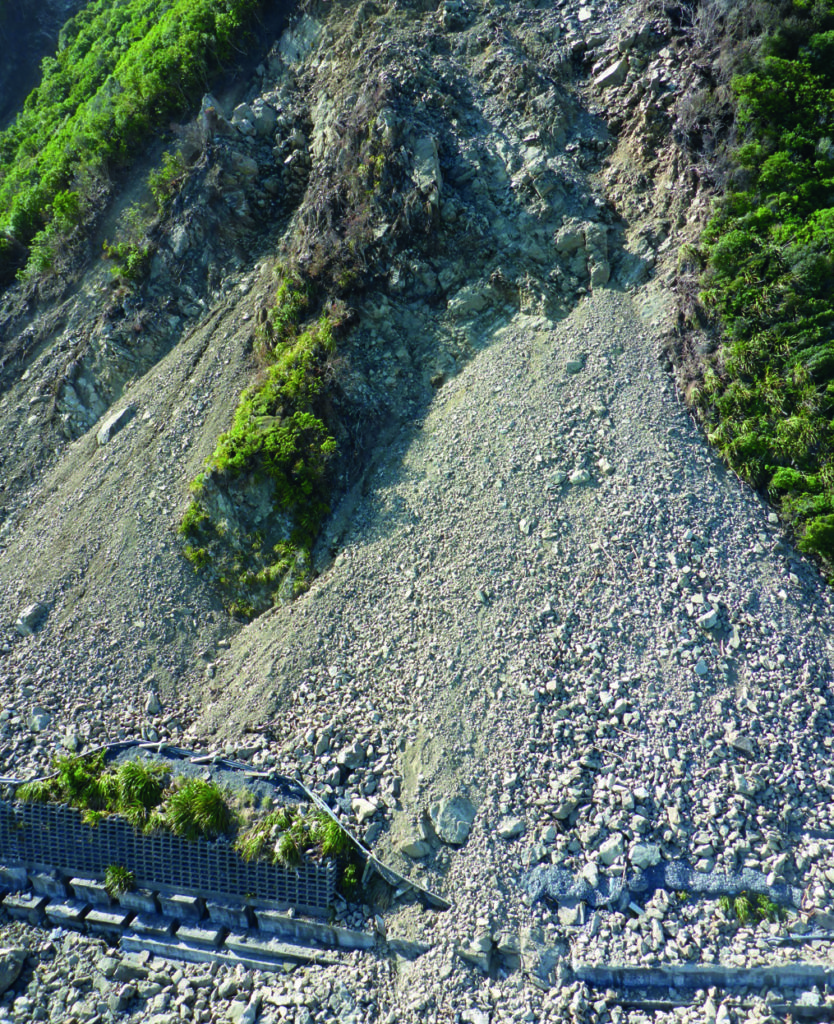
Figure 8: Shallow failure at head of slip P2 with debris cones burying SH1

Figure 8: Shallow failure at head of slip P2 with debris cones burying SH1

Conversely, quite small rainfall events have initiated debris flows from the secondary failures and erosion on the primary landslide slopes. The debris flows have deposited new debris on the road and rail links and discharged via culverts onto the foreshore. The rainfall associated with Cyclone Debbie (April 2017) emphasised that debris flows will continue to be a problem until source areas revegetate and that under-sized culverts will be blocked by debris (Figure 10).

Figure 10: Debris flow onto SH1 and foreshore following heavy rain in April 2017.

A key outcome from our work to date has been an assessment of hazard and risk along the transportation corridor to identify the ongoing hazards and high risk locations. This information is based on the work described above. It is being used in the development of engineering solutions to manage both construction risks and long term risk to the road and rail users to a level that is as low as reasonably practicable (ALARP).
Following sluicing and rock removal works, slip clearing work to date has involved top down removal of talus cones to recover the road and rail, or to make it safe to realign road and/or rail at some locations (Figure 11). The details of alignment changes and risk mitigation measures are still being finalised at the time of writing, but are likely to involve rockfall and debris catch ditches, bunds and barriers.

Figure 11: Slip P1A, North Kaikoura coast – before, during and after debris removal from SH1. Note progressive failure of the ‘tree island’

