
This article introduces reinforced soil structures, their ductile characteristics, research and full-scale trials carried out on the rockfall impact ability. Two recent projects in Christchurch involving Green Terramesh reinforced soil bunds are presented. They are designed with the aim to withstand dynamic impacts caused by high kinetic energy rockfall impacts and debris flow impacts.
Introduction
Reinforced soil can be defined as a soil mass containing multiple layers of horizontally laid planar reinforcement. The use of reinforced soil is increasing on a worldwide scale. Engineers are attracted by the greater reliability and control arising from the uniform properties of modern reinforcement, and the ability of reinforcement elements to strengthen local soil and offset the effects of defects.
The three major components that make up a reinforced soil structure are:
- Soil fill – compacted structural fill material from
front facing to rear of reinforcement - Reinforcement element – such as polymer geogrids, double twist steel mesh
- Facing element – to protect the reinforced soil
mass against natural degradation
Each component is essential in ensuring the structure performs according to the design requirements for both ultimate and serviceability limit state.
The soil mass combined with reinforcement elements exhibits vastly enhanced strength and deformation properties and provides greater ability to resist forces. This is due primarily to the increased ductility of the reinforced soil mass. In materials, ductility refers to the ability of a material to deform under tensile stresses; unreinforced soil generally has little to no ability to withstand tensile stresses. Closely spaced reinforcement added to soil provides additional internal strength and increases stiffness properties due to surface interaction between the reinforcement element and soil.
The majority of the reinforced soil applications worldwide involve walls and slopes supporting infrastructure. Most design code of practices (such as AS4678:2002; FHWA and BS8006:2010) provide detailed design requirements for internal and external stability in accordance to the importance level of the structure and loading type.
This article focusses on a more recent and less common use of reinforced soil where it is used in structures built to resist dynamic impact loads imposed by falling rocks or flowing debris. Unlike for other reinforced soil structures, there are currently no widely accepted design codes of practice for these types of structures; to date, these types of structures are designed on the basis of physical testing, numerical modelling and back-analysis of the performance of existing structures.
Two examples of these types of structures built in Christchurch are presented and discussed.
Design of reinforced soil for resisting dynamic impacts
Reinforced soil structures (or bunds) are able to absorb high energy impacts while maintaining structural integrity. Considerable research and full scale trials have been carried out on reinforced soil bunds in an effort to develop and refine design parameters.
The design of the reinforced soil bund is primarily based on the penetration depth of an impacting rock based on its kinetic energy and size; the penetration depth largely determines the required thickness of the bund. The relationship between penetration depth and boulder sizes with their kinetic energy has been derived in a simplified chart developed by Calvetti & Di Prisco (2007), see Figures 1 and 2. This chart has been developed on the basis of FEM analysis, full scale trials on reinforced soil bunds and back analysis of actual events. The design approach and considerations have been covered by many technical papers and publications.

Figure 1: FEM modelling of the impact of a cubic, rigid body on a Green Terramesh reinforced soil embankment

Figure 2: Derived maximum penetration of an impacting block in relation to impact energy (Galvetti and Di Prisco, 2007)

Photo 1: Real case ‘piercing impact’ on Green Terramesh reinforced soil bund
The research findings and investigation of actual rockfall events have shown that the key mechanism involved in stopping a high energy rock impact is dissipation of energy during formation of a crater in the upslope side of the bund. It is reported that 80-85% of the energy dissipation is through this plastic deformation while the remaining energy dissipates through frictional loss. Photo 1 indicates a piercing impact of an estimated 7500kJ rock impact energy on a Green Terramesh reinfoced soil bund; the edge of the bund was not affected by this impact indicating high energy absorption and ductility characteristics. There are exising bunds that have been designed to received impact energy of >15,000 kJ.
Project 1- Sumner Road, Wakefield Avenue Rockfall Protection Bund
During the 2010/11 Canterbury earthquake sequence, the Sumner area experienced rockfall, cliff collapse and landslides. Wakefield Avenue in Sumner is part of an important transportation link from Lyttelton (the port of Christchurch) to Sumner and Christchurch. Christchurch City Council, as part of the Summer-Lyttelton Corridor project, has identified four major sections along the route where it is necessary to mitigate the slope instability risks to an acceptable level for road users. Wakefield Avenue is one of the sections.
The primary objective of the Wakefield Avenue project is to mitigate rockfall risk posed by three rock source areas scattered some hundreds of meters away on the slope above a total affected length of 1.2 km of Wakefield Avenue. Fallen blocks of up to 2.0 m nominal diameter have been observed at site. Trajectory analysis and post-earthquake observations indicate that falling rocks have impacted the road and that there is a risk that they could reach the residential zone across the road.
Initial attempts to mitigate the risk by scaling and removing the loose rocks on the slope were judged not to be feasible after subsequent earthquakes resulted in additional rockfall and caused further damage to the cliffs and rock bluff source areas. It was not considered practical to undertake scaling works over the large source area, nor was there any certainty that scaling would successfully treat the problem as it was unknown how far the damage extended into the rock mass. Mesh draping over the entire source area to control the rockfall was deemed to be cost prohibitive due to the large surface area for meshing. Rockfall analyses were performed by the engineers (Jacobs New Zealand Limited) on various sections along Wakefield Avenue. The final decision was made to construct rockfall protection structures atthree locations to intercept the falling rocks. This paper primarily discusses the longest bund, 410m long. The other bunds are 132m and 26m in length.
The two alternatives considered were an ETAG 27 certified catch fence and reinforced soil bunds. In this instance, the reinforced soil bund option was selected on the basis of the following reasons:
- Lower whole life cost
- Ability to withstand multiple impacts
- Easier maintenance and repair after each rockfall event without the need of replacement
- No setback needed to allow for horizontal displacement of structure
- Blends well with the environment
- Design life more than 50 years
The rockfall anlysis data was collated into three major categories based on the boulder sizes, bounce height and kinetic energy based on the design 95th percentile boulder size. The input data for the bund geometry determination is summarized in Table 1 below:

Table 1: GTM bund input data provided from trajectory analysis
The final results are Green Terramesh bunds with three different heights ranging from 3.6 m to 6.0 m and face inclinations of 70° or 80°. Along the different sections of the bund, choices of surface finish will consist of rock fill face and vegetated or planted face.
The adopted ‘facing unit’ for the reinforced soil bund is a Green Terramesh (GTM) unit. Figure 3 shows the isometric view of the unit. For lower height, narrower structures the soil reinforcement is comprised of the 2 m long double twist PVC Galfan (Zn + 5% Al) coated mesh ‘tail’ that extends along the base length of the unit; this forms a continuous layer between the upslope and downslope facing units. For taller, wider structures, additional geogrid reinforcement is included in between unit heights and to connect between the 2m-long tails from the opposing faces. The mesh is continuous from the base to the upper lid and the units are connected with stainless steel rings during construction.

Figure 3: Green Terramesh Unit
One of the key benefits of the Green Terramesh unit is the ability to undertake local repairs after rock impacts without affecting the reinforced soil bund structural integrity. Repairs can be undertaken for penetration depths of <20 % of the bund thickness or usually < 500-700 mm of upslope deformation. This is the serviceability limit state of the bund. A similar double twist mesh layer can be laced over the impacted area so that the structure will be ready for subsequent impacts.
At the time of writing, the construction of the GTM bund by HEB Construction is still in progress (Photos 2 to 4) with the completion expected at the end of November 2016.

Photo 2: GTM bund 1 in Wakefield Avenue (before vegetation)
Photo 3: Cross section view of the Green Terramesh bund in Wakefield Avenue before filling


Photo 4: Green Terramesh bund 2 in Wakefield Avenue (rockfill face)
Project 2- Maffeys Road Mass Movement Protection Bund
Following the 2010/11 Canterbury earthquake sequence, the loess slope below Maffeys Road was identified by GNS Science as one of the areas with a high risk of mass movement that could affect properties and infrastructure down slope. The potential failure mechanism was identified as shallow sliding of overlying loess on top of the basalt bedrock surface. Instead of undertaking slope stabilization works, it was decided that a protection barrier should be constructed to partially deflect, intercept and contain the loess slope in the event of failure. AECOM were retained as the designers and worked closely with Geofabrics. Limited space available between the slope toe and properties meant that a reinforced soil protection bund had to be used to reduce the footprint and increase the containment volume.
- In addition to the footprint consideration, the design of the reinforced soil bund had to fulfil a number of technical requirements:
- The protection bund has to be able to withstand, without toppling failure, the dynamic impact of debris flow impact at 5 m/s
- The protection bund must be able to be partially repaired or patched should any of the section be impacted
- The protection bund must have proven records of use
- It has to be durable (typically >50 years)
- There has to be very minimal maintenance required
The Green Terramesh reinforced soil bund was adopted because it meets all of these design requirements.
One of the design requirements is that the protection bund must resist the dynamic impact load from the mass soil movement. This mass soil movement was treated as a debris flow consisting of impact waves (resulting in dynamic forces) and consolidation of the material on the upslope side (resulting in static forces). Based on a velocity of 5 m/s with estimated saturated soil weight of 20 kN/m3, the dynamic pressure was calculated to be approximately 100 kPa through the use of an empirical formula provided by Hong Kong GEO “DN1/2012- Suggestions on Design Approaches for Flexible Debris-resisting Barriers”. This dynamic pressure is further reduced since it will impact on a 70 degree inclined face upslope.
In this case, wave height has been assumed and slope stability software (MacStars) has been used to simulate several phases of the dynamic and static. Figure 4 shows a snapshot of the internal stability analysis result with accumulated static debris load and dynamic pressure acting at the upslope side of the bund.

Figure 4: Macstars stability analysis snapshot of 5.4m high Green Terramesh bund
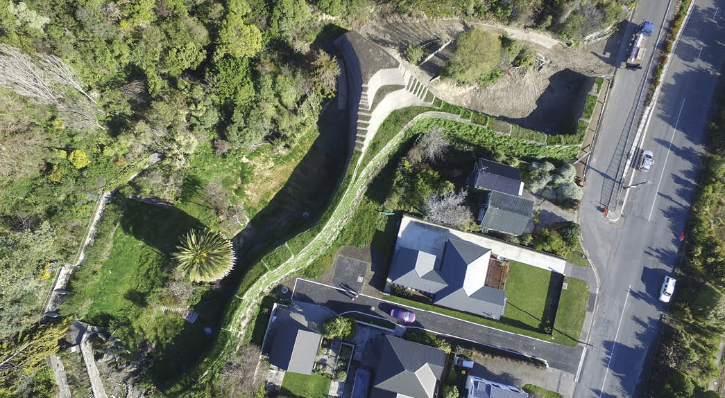
Photo 5: Area view of Green Terramesh bund in Maffeys Road (photo courtesy of Fulton Hogan)

Figure 5: Macstars stability analysis snapshot of the apex section

Photo 6: Front view of GTM bund in Maffeys Road

Photo 7: Side view of Green Terramesh bund in Maffeys Road
The alignment of the Green Terramesh bund (Photo 5) incorporates an apex nearer to the source area to divert and deflect the soil mass to either side of the apex. This approach was selected by AECOM to separate the soil mass and thereby significantly reduce the required bund height. Constructing the apex near the main source area means that the landslide mass is intercepted after a much shorter travel distance, reducing the dynamic impact pressure. The long curve shape layout of the bund left and right of the apex is aligned at an angle to the impact direction, which further reduces the dynamic impact pressure. The long bund layout helps to contain the debris volume allowing for clearing as well as minimising the height of the bund.
The apex structure in the centre is a reinforced soil structure with total height of 14.4 m. Seismic and static internal and global stability analysis (Figure 5) have been performed to ensure the structure is self-stable under its own weight. Internal/compound stability factor of safety under the reduced seismic horizontal acceleration of 0.26g for ductile structure was found to be >1.1. Static stability analysis factor of safety was in excess of 1.7.
The Green Terramesh bund construction took the contractor (Fulton Hogan) approximately 1 year and was completed in early August 2016.

References
- Brunet, G., Giacchetti G and Bertolo P (2009). Protection for high energy rockfall impacts using Terramesh embankments: Design and experiences. Proceedings 60th Highway Geology Symposium, Buffalo, New York pages 107-124
- AECOM (2015). Final design report- Port Hills mass movement remediation: Maffeys Road protection barrier. AECOM New Zealand Ltd
- Christchurch City Council (2015). Sumner Lyttelton Corridor – geotechnical risk mitigation works
- Grimod, A. and Giacchetti, G. (2013). Protection from high energy impacts using reinforced soil embankments: Design and experiences. In: Landslide Science and Practice, Vol.3: Spatial Analysis and Modelling, pp 189-196 DOI 10.1007/978-3-642-31310-3_26
- Jacobs (2015). Sumner-Lyttelton Corridor Geotech Design Report: Wakefield Avenue. Jacobs New Zealand Limited.
- Kwan, J.S.H. & Cheung, R.W.M. (2012). Suggestions on Design Approaches for Flexible Debris-resisting Barriers (DN 1/2012). Geotechnical Engineering Office, Hong Kong, 90 p.
- Maccaferri (2011). Technical note – Green Terramesh rockfall protection embankments, Maccaferri New Zealand
The approval of Christchurch City Council, Jacobs and AECOM to publish this article is gratefully acknowledged. And I particularly thank Rori Green for her editorial efforts.

